Notifier Wheelock Series SM and SMX Synchronization (Sync) Module

File Preview
Click below to download for free
Click below to download for free
File Data
| Name | notifier-wheelock-series-sm-and-smx-synchronization-sync-module-7108549623.pdf |
|---|---|
| Type | |
| Size | 964.30 KB |
| Downloads |
Text Preview
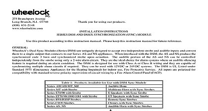
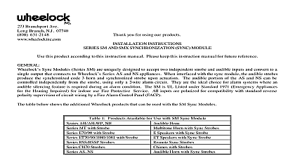
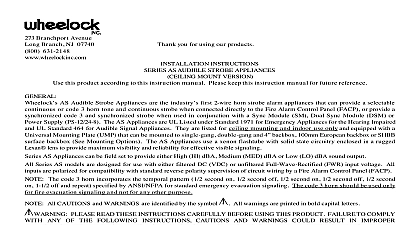
Branchport Ave Branch N J 07740 631 2148 Thank you for using our products INSTRUCTIONS SM AND SMX SYNCHRONIZATION SYNC MODULE this product according to this instruction manual Please keep this instruction manual for future reference Sync Modules Series SM are uniquely designed to accept two independent strobe and audible inputs and convert to a output that connects to Wheelock Series AS and NS appliances When interfaced with the sync module the audible strobes the synchronized code 3 horn and synchronized strobe upon actuation The audible portion of the AS and NS can be independently from the strobe using only a 2 wire alarm circuit They are the ideal choice for alarm systems where an silencing feature is required during an alarm condition The SM is UL Listed under Standard 1971 Emergency Appliances the Hearing Impaired for indoor use Fire Protective Service All inputs are polarized for compatibility with standard reverse supervision of circuit wiring by a Fire Alarm Control Panel FACP table below shows the additional Wheelock products that can be used with the SM Sync Modules 1 Products Available for Use with SM Sync Module AH AH WP NH MT with Strobe E70 90 with Strobe ET70 90 1080 1081 with Strobe RSS RSSP Strobes CH70 Strobes AS NS Horn Horn with Sync Strobes Speakers with Sync Strobe Speakers with Sync Strobe Sync Strobes with Strobes Horn with Sync Strobes All CAUTIONS and WARNINGS are identified by the symbol All warnings are printed in bold capital letters READ THESE INSTRUCTIONS CAREFULLY CAUTIONS AND WARNINGS COULD RESULT FAILURE TO COMPLY WITH ANY OF THE APPLICATION AND OR OPERATION OF THESE PRODUCTS IN AN EMERGENCY SITUATION WHICH COULD IN PROPERTY DAMAGE AND SERIOUS INJURY OR DEATH TO YOU AND OR OTHERS 2 Ratings Per UL 1971 VDC SMX is a UL recognized component without a mounting plate THESE APPLIANCES WERE TESTED TO THE OPERATING VOLTAGE LIMITS OF 8 33 VOLTS FILTERED DC OR UNFILTERED FULL WAVE RECTIFIED FWR DO NOT APPLY 80 AND 110 OF VOLTAGE VALUES FOR SYSTEM OPERATION CHECK THE MINIMUM AND MAXIMUM OUTPUT OF THE POWER SUPPLY AND STANDBY AND SUBTRACT THE VOLTAGE DROP FROM THE CIRCUIT WIRING RESISTANCE TO DETERMINE APPLIED VOLTAGE TO THE STROBES 2001 Wheelock Inc All rights reserved N 1 of 6 3 Sync Module Current Requirement AMPS Average Peak Inrush Time duration for the peak and inrush current is 6 milliseconds MAKE SURE THAT THE TOTAL CURRENT REQUIRED BY ALL APPLIANCES THAT ARE TO A SYNC CONTROL MODULE DOES NOT EXCEED 3.0A OR EXCEED THE RATING OF THE FIRE CONTROL PANEL PRIMARY AND SECONDARY POWER SOURCES AND NAC CIRCUITS THESE SOURCES COULD RESULT IN LOSS OF POWER AND FAILURE TO ALERT OCCUPANTS AN EMERGENCY WHICH COULD RESULT IN PROPERTY DAMAGE AND SERIOUS INJURY OR DEATH YOU AND OR OTHERS calculating the total average peak or inrush currents Use Table 3 to determine the highest value of Average Current an individual strobe across the expected operating voltage range of the strobe to determine the highest value of Inrush or Peak Current whichever is higher of an individual strobe across the expected voltage range of the strobe then the value by the total number of strobes be sure to add the currents for any other appliances including audible signaling powered by the same source and include any required safety factors the inrush current or peak current exceeds the power supplies inrush capacity the output voltage provided by the power supplies drop below the listed voltage range of the appliances connected to the supply and the voltage may not recover in some types of supplies For example an auxiliary power supply that lacks filtering at its output stage either via lack of capacitance and or of battery backup across the output may exhibit this characteristic INFORMATION Non sync appliances can be installed before or after an SM or DSM If the non sync appliance requires audible silence four connection is necessary with the strobe circuit connected before the SM or DSM NAC circuit and the audible leads connected to silenceable NAC circuit from the FACP Power Supply may be used in conjunction with the SM Sync Modules ONLY in the order shown in Figure 1 Only SM Sync Module shall be allowed on a signaling circuit Do not connect the Power Supply to the signaling circuit after the one Sync Module Exception The Wheelock PS 12 24 8 Power Supply can be connected either before or after the SM Sync Module to Power Supply instruction manuals for proper application or installation 1 SM Connection Diagram with Power Supply OR STROBE N 2 of 6 A 1 Wiring Diagrams for the appliance Series AS NS NH and AH 2 Class Circuit with Audible Silence Feature MODULE SIGNAL 1 SIGNAL 1 NEXT APPLIANCE EOLR Appliances draw power from strobe appliance circuit only 3 Class Circuit without Audible Silence Feature Red and Black Shunt Wires are Supplied EOLR STROBE MODULE MODULE 1 NEXT APPLIANCE EOLR A 2 Wiring Diagram for the Sync Strobes Series RSS RSSP MT CH and Series E ET 4 Wiring Diagram for Sync Strobes Red and Black Shunt Wires are Supplied 1 NEXT SYNC OR EOLR DO NOT CONNECT THE MULTITONE AUD TERMINALS TO THE OUTPUT OF AN SM OR DSM AUDIBLE MAY STOP SOUNDING AS A RESULT A FOUR WIRE CONFIGURATION SHOULD BE USED WITH AUD TERMINALS CONNECTED TO A SEPARATE SIGNAL CIRCUIT N 3 of 6 Modules have in out wiring terminals that accepts two 12 to 18 AWG wires at each screw terminal Strip leads 3 8 inches for to screw terminals Break all in out wire runs on supervised circuits to assure integrity of circuit supervision shown in 5 The polarity shown in the wiring diagrams is for the operation of the appliances The polarity is reversed by the FACP supervision Install the appliance to a grounded backbox Per NFPA 70 the National Electrical Code using the lockwashers in hardware bag under the head of each mounting screw for the appliance OPTION 5 A X 2 1 8 BACKBOX 8 32 X 1 SCREWS NUMBER OF CONDUCTORS 18 AWG 16 AWG 14 AWG 12 Figure A shows the maximum number of field wires conductors that can enter the backbox used with this mounting If these limits are exceeded there may be insufficient space in the backbox to accommodate the field wires and stresses from wires could damage the product N 4 of 6 NOTES Check that the installed product will have sufficient clearance and wiring room prior to installing backboxes and especially if sheathed multiconductor cable or 3 4 conduit