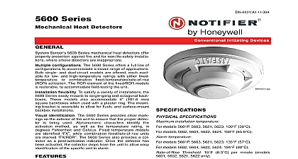
System Sensor 5600 Series Mechanical Heat Detector – Installation Manual

File Preview
Click below to download for free
Click below to download for free
File Data
| Name | system-sensor-5600-series-mechanical-heat-detector-installation-manual-8967512043.pdf |
|---|---|
| Type | |
| Size | 1.03 MB |
| Downloads |
Text Preview
INSTALLATION AND MAINTENANCE INSTRUCTIONS Series Heat Detector Circuit 5601 5602 5603 5604 Circuit 5621 5622 5623 5624 Installing detector must be installed in compliance with the con panel installation manual and meet the requirements of 72 and or the local authority having jurisdiction this manual carefully before using the detector This should be left with the owner user of this equip Description 5600 series mechanical heat detector is intended use in property protection applications or for non installations where smoke detection is not practi or appropriate life safety installations smoke detectors must be used lieu of or in addition to mechanical heat detectors 5600 series consists of both single and dual circuit detectors featuring fixed temperature thermal sensors combination fixed temperature rate of rise sensors with ratings of 135 57 or 194 90 on the exterior of the detector indicate the spe activation method and temperature rating All models identified as either 135 or 194 Models with combination fixed temperature rate of rise are marked FX ROR Fixed temperature only mod are marked FX 57 90 Sensor Temperature of Rise Temperature of Rise Maximum ceiling x 50 feet x 50 feet 57 Temperature x 25 feet 90 Temperature x 25 feet 57 90 Temperature of Rise Temperature of Rise x 50 feet x 50 feet 57 Temperature x 25 feet 90 Temperature x 25 feet 1 5600 Series Mechanical Heat Detectors Refer to NFPA72 guidelines for spacing reductions ceiling heights exceed 10 feet 3825 Ohio Avenue St Charles Illinois 60174 FAX 630 377 6495 Fixed Temperature Sensor fixed temperature element reacts to heat by respond to a specific temperature setting 135 or 194 The method is based on the spring action of a metal held to the metal chamber by a fusible alloy the temperature reaches the alloy melting point metal contact will depress the diaphragm causing the contact to close the circuit The circular external collector is released from the detector to visually indi that the detector has been activated 5600 series Fixed Temperature models 5603 5604 and 5624 are non resettable and cannot be tested Rate of Rise ROR Sensor rate of rise element responds to a rapid rise of temper approximately 15 8.3 per minute As the tem rises the air within the sealed chamber expands the chamber air expand faster than it can escape the calibrated vent the diaphragm is depressed the electrical contact closes the circuit Only the ROR element of 5600 series combination temperature ROR models 5601 5602 5621 and are self restoring and may be tested using a hair or heat gun When testing the ROR element to pre the activation of the fixed temperature element the source must not exceed the fixed temperature rating the detector Bracket 5600 series detectors are equipped with a mounting that includes mounting slots to accommodate 31 octagonal and 4 octagonal electrical as well as 4 square boxes equipped with a plas ring Figure 1 The mounting bracket is reversible to flush mount and surface installa Figure 2 31 Octagonal box 4 Octagonal box Single gang box and 4 square with plaster ring Directly to Wall Ceiling GAUGE 1 I56 2175 00R 1 Bracket Mounting Locations refer to insert for the Limitations of Fire Alarm Systems Limited Warranty Sensor warrants its enclosed module to be free from defects in materials and under normal use and service for a period of three years from date manufacture System Sensor makes no other express warranty for this module agent representative dealer or employee of the Company has the authority to or alter the obligations or limitations of this Warranty The Company obli of this Warranty shall be limited to the replacement of any part of the module is found to be defective in materials or workmanship under normal use and during the three year period commencing with the date of manufacture After System Sensor toll free number 800 SENSOR2 736 7672 for a Return number send defective units postage prepaid to System Sensor Department RA 3825 Ohio Avenue St Charles IL 60174 include a note describing the malfunction and suspected cause of failure Company shall not be obligated to replace units which are found to be defective of damage unreasonable use modifications or alterations occurring after date of manufacture In no case shall the Company be liable for any consequen or incidental damages for breach of this or any other Warranty expressed or whatsoever even if the loss or damage is caused by the Company negli or fault Some states do not allow the exclusion or limitation of incidental or damages so the above limitation or exclusion may not apply to you Warranty gives you specific legal rights and you may also have other rights vary from state to state device complies with part 15 of the FCC Rules Operation is subject to the following two conditions 1 This device may not cause harmful interference and 2 this must accept any interference received including interference that may cause undesired operation This equipment has been tested and found to comply with the limits for a Class B digital device pursuant to Part 15 of the FCC Rules These limits are designed to reasonable protection against harmful interference in a residential installation This equipment generates uses and can radiate radio frequency energy and if installed and used in accordance with the instructions may cause harmful interference to radio communications However there is no guarantee that interference not occur in a particular installation If this equipment does cause harmful interference to radio or television reception which can be determined by turning the off and on the user is encouraged to try to correct the interference by one or more of the following measures Statement Reorient or relocate the receiving antenna Increase the separation between the equipment and receiver Connect the equipment into an outlet on a circuit different from that to which the receiver is connected Consult the dealer or an experienced radio TV technician for help 4 I56 2175 00R System Sensor a After all detectors have been installed apply power the alarm control unit Test each detector as described in Testing Reset all the detectors at the alarm control unit Notify the proper authorities that the system is in oper ation 2 Reversible Mounting Bracket Installation Guidelines wiring must be installed in compliance with the Electrical Code applicable state and local codes any special requirements of the local Authority Having Proper wire gauges should be used The used to connect heat detectors to the alarm panel and accessory devices should be color coded reduce the likelihood