Potter BSC Break Safe Contacts

File Preview
Click below to download for free
Click below to download for free
File Data
| Name | potter-bsc-break-safe-contacts-4302781695.pdf |
|---|---|
| Type | |
| Size | 1.28 MB |
| Downloads |
Text Preview
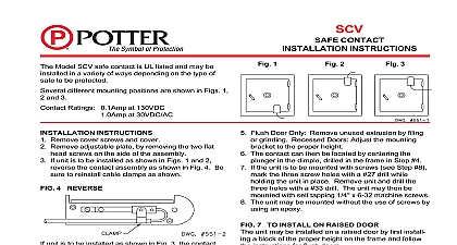
BSC SAFE CONTACTS Listed Assembly 3.06 L x 2.19 W x 1.63 H L x 5,6cm W x 4,1cm H 4.13 L x 1.75 W x 1.19 H L x 4,4cm W x 3,0cm H 11 oz 308 g Base and Plunger Assembly Acid treated alumi Baked grey spatter enamel parts nickel plated to resist corrosion Blade Contacts Silver Contacts Gold Treated Copper SPDT Form C Amp at 130VDC Amp at 30VDC AC Mechanically activated when base is removed safe body Limitations Indoor use only 2 MOUNTING ADJUSTMENT No 2020001 Model BSC Break Safe Contact is exterior mounted proof and operates with open closed or double Model BSC can be mounted in several positions on the style of safe by simply loosening the set in the plunger assembly See Figures 1 and 2 set screws are tightly secured after repositioning assembly base is mounted on the safe body and the plunger is on the door See Figure 3 The wire entrance to base is threaded to accept a 1 2 conduit fitting EVD Bulletin for complete safe protection 1 BSC TYPICAL SAFE INSTALLATION 3 INTERNAL CONTACT DRAWING DOOR SAFE DOOR SAFE ON DOUBLE DOOR SAFES DOORS MUST HAVE FOR UL CERTIFICATED FOR SAFES WITH ROUND SEE SCV BULLETIN Electric Signal Company 2081 Craig Road St Louis MO 63146 4161 Phone 800 325 3936 Canada 888 882 1833 www pottersignal com IN USA 8870003 REV G 5400703 12 01 1 OF 2 SAFE CONTACTS installing the BSC in an EVD C pickup loop normally closed only the BSC is installed in an EVD C pickup loop it must be wired in series before the last EVD P on the loop wire from terminal 4 of the EVD C goes to the common center contact of the BSC normally closed bottom contact would go to terminal 2 of the EVD P shield from terminal 3 of the EVD would connect to the normally open top contact then continue to terminal 1 the EVD P it is wired directly to the relay contacts on any EVD a normally open circuit that shorts on alarm EOL resistor from burglar panel across N O and N C top and bottom contacts N O top contact to the N O relay contact of the EVD common center to the N C relay contact of the EVD zone of burglar panel to the common and N O relay contacts of the EVD See Fig 4 4 5 a normally closed circuit that opens on alarm EOL resistor from burglar panel across N O and common top and center contacts N O top contact to the N O relay contact of the EVD N C bottom contact to the common relay contact of the EVD zone of burglar panel to the N O and N C relay contacts of the EVD See Fig 5 IN USA 8870003 REV G 5400703 12 01 2 OF 2