Potter CHS Series Selectable Candela Ceiling Mount Horn Strobe

File Preview
Click below to download for free
Click below to download for free
File Data
| Name | potter-chs-series-selectable-candela-ceiling-mount-horn-strobe-9147230658.pdf |
|---|---|
| Type | |
| Size | 1.22 MB |
| Downloads |
Text Preview
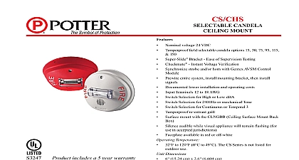
Features Nominal voltage 24 VDC field selectable candela options 15 30 75 95 115 150 Bracket Ease of Supervision Testing Instant Voltage Verification strobe and or horn with Gentex AVSM Control entire system install mounting bracket then install Documented lower installation and operating costs Terminals 12 to 18 AWG Selection for High or Low dBA Selection for 2400Hz or mechanical Tone Selection for Continuous or Temporal 3 re entrant grill mount with the CLNGBB Ceiling Surface Mount Back audible while visual appliance will remain flashing for in accepted jurisdictions available in red or off white Temperature to 120 0 to 49 The CS Series is not listed for use Dimensions 15.24 cm x 2.6 6.604 cm Ceiling Mount Series comes standard with the 4 mounting plate incorporates the popular Super Slide feature that allows the to easily test for supervision The product also features a mechanism which secures the product to the bracket without screws showing CS CHS also features the patented Checkmate Instant Voltage feature which allows the installer to check the voltage drop without removing the signal CS Series appliances are ANSI UL 464 and ANSI UL 1971 listed use with fire protective systems 1 OF 4 includes a 5 year warranty Potter CS CHS Series is a ceiling mount strobe or horn strobe that offers dependable audible and visual alarms and the current consumption CS CHS offers tamperproof field selectable candela options of 15 75 95 115 and 150 candela CHS horn offers a continuous or synchable temporal three in and mechanical tone All tones are easy for the professional to in the field by using switches The models are shipped from the in the temporal three alarm mode CS Series has a very minimal operating current and has a minimum rate of 1Hz regardless of input voltage 8830051 REV A06 13PRINTED IN USACS CHSSELECTABLE CANDELA CEiLiNg mouNTPotter Electric Signal Company LLC St Louis MO 63042 USA Cust Service 866 572 3005 Tech Support 866 956 0988 Canada 888 882 1833 www pottersignal comfirealarmresources com Super Slide Snap Cover Over Assembly Insert Locking Screw Slide Onto Bracket Instant Voltage Verification Locations access holes are provided in the back of the terminal block to the voltage to be measured directly without removing the Typically this would be done at the end of the line to confirm criteria Most measurements will be taken using the S and locations although access is provided to other locations NOTICE SHOULD BE TAKEN TO NOT SHORT THE TEST PROBES positions 1 and 2 in the down position to select isolated horn strobe power inputs Switch 3 selects between temporal or non tone Up is temporal Switch 4 selects between mechanical or frequency tone Up is mechanical Switch 5 selects between high low dBA Up is high dBA 2 OF 4 8830051 REV A06 13PRINTED IN USACS CHSSELECTABLE CANDELA CEiLiNg mouNTPotter Electric Signal Company LLC St Louis MO 63042 USA Cust Service 866 572 3005 Tech Support 866 956 0988 Canada 888 882 1833 www pottersignal comfirealarmresources com Series 24 Volt Ceiling Mount Selectable Strobe VDC VDC VDC VDC 30 75 95 115 150 30 75 95 115 150 30 75 95 115 150 30 75 95 115 150 VDC VDC VDC VDC 30 75 95 115 150 30 75 95 115 150 30 75 95 115 150 30 75 95 115 150 Designations Ceiling Mount Red Faceplate Strobe White Faceplate Horn Strobe units are available in plain no lettering units are non returnable Product Strobe Current Ratings mA Series 24 Volt Ceiling Mount Selectable Horn Strobe dBA ft per ANSI UL 464 Anechoic Room 10 ft VDC Volts VDC Max1 cd cd cd mA 101 mA 167 mA mA 120 mA 200 mA cd mA mA cd mA mA cd mA mA Product Horn Decibel and Current Ratings mA dBA 10 ft dBA 10 ft ANSI UL 464 ANSI UL 464 24 VDC Operating High Setting mA 3 2400Hz 3 Mechanical 2400Hz Mechanical sound output for the temporal 3 tone is rated lower since the time the horn is off is averaged into the sound output rating While the is producing a tone in the temporal 3 mode its sound pressure is the same as the continuous mode nominal and peak current across UL regulated voltage range for filtered DC power and unfiltered FWR Full Wave Rectified power installation manual does not recommend using a coded or pulsing signaling circuit with any of our strobe products Operating the horn in this mode at this voltage will result in not meeting the minimum ANSI UL 464 reverberant sound level required for mode fire protection service These settings are acceptable only for private mode fire alarm use Use the high dBA setting for public application not applicable when using the chime tone The chime tone is always private mode current ratings are per UL average RMS method UL max current rating is the maximum RMS current within the listed voltage range for 24VDC units For strobes the UL max current is usually at the minimum listed voltage 16VDC for 24VDC units For the max current is usually at the maximum listed voltage For unfiltered FWR ratings see installation manual 3 OF 4 8830051 REV A06 13PRINTED IN USACS CHSSELECTABLE CANDELA CEiLiNg mouNTPotter Electric Signal Company LLC St Louis MO 63042 USA Cust Service 866 572 3005 Tech Support 866 956 0988 Canada 888 882 1833 www pottersignal comfirealarmresources com Engineering Specifications Inc per ANSI UL 1971 for the GCS and ANSI UL 464 for the GCC The notification appliance shall also be listed with the State Fire Marshal CSFM visible and audible visible signal shall be Gentex model GCS or GCC or approved equal and shall be listed by Underwriters notification appliance combination audible visible units and audible units only shall produce a peak sound output of 90dBA or as measured at 24VDC in an anechoic chamber The signaling appliance shall also have the capability to silence the audible signal while the visible signal energized with the use of a single pair of power wires Additionally the user shall be able to select either continuous or tone output with the temporal signal having the ability to be synchronized voltage The appliance shall have an operating current of 72mA or less at 24VDC for the 15 candela strobe circuit audible visible and visible signaling appliance shall also maintain a minimum flash rate of 1Hz or up to 2Hz regardless of power appliance shall be polarized to allow for electrical supervision of the system wiring The unit shall be provided with a mounting with terminals with barriers for input output wiring and be able to mount to a single gang or double gang box or double workbox with use of an adapter plate The unit shall have an input voltage range of 16 33 volts with either direct current or full wave rectified power to a surface back box appliance shall be capable of test supervision without disconnecting wires verify voltage without removing unit and be capable of CS CHS Series Wiring Diagrams All strobes are designed to flash as specified with continuous applied voltage Strobes should not be used on coded or pulsing signaling However use of the Gentex AVSM control module or Gentex synchronization protocol is permitted to synchronize the strobe horn mute the horn SYNCHRONIZATION WIRING INFORMATION REFERENCE AVSM CONTROL MODULE DATA SHEET 8830050 AVSM CONTROL MODULE MANUAL FOR SYNCHRONIZATION MODULE WIRING DIAGRAMS AVSM MODULE DATA SHEET AND MANUAL CAN BE OBTAINED AT http www pottersignal com OR CALL POTTER AT 1 800 325 3936 4 OF 4