Potter IInstallation Manual Detector Bases PAD100-IB, PAD100-RB & PAD100-SB

File Preview
Click below to download for free
Click below to download for free
File Data
| Name | potter-iinstallation-manual-detector-bases-pad100-ib-pad100-rb-pad100-sb-7802915364.pdf |
|---|---|
| Type | |
| Size | 2.42 MB |
| Downloads |
Text Preview
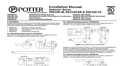
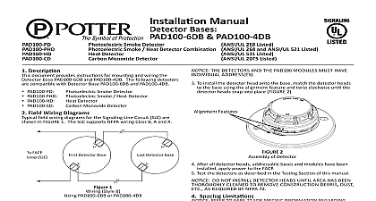
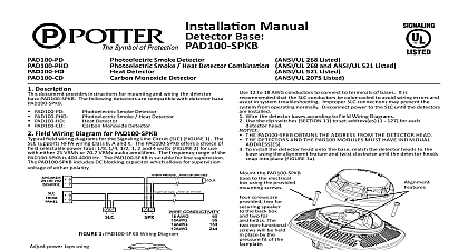
Installation Manual Bases PAD100 RB PAD100 SB Smoke Detector Smoke Heat Detector Combination ANSI UL 268 and ANSI UL 521 Listed Detector Monoxide Detector 521 Listed 2075 Listed 268 Listed Description document provides instructions for mounting and wiring the Detector Bases PAD100 RB and PAD100 SB The following detectors are compatible Detector Bases PAD100 IB PAD100 RB and PAD100 SB PAD100 PD PAD100 PHD PAD100 HD PAD100 CD Field Wiring Diagram s for PAD100 IB field wiring diagrams for the Signaling Line Circuit SLC are shown in 1 The SLC supports NFPA wiring Class B A and X Smoke Detector Smoke Heat Detector Detector Monoxide Detector SLC2 Base SLC2 SLC2 Base FACP SLC BASE BASE MODULE AREA TO BE ISOLATED BY THE SHORT CIRCUIT CIRCUIT 1 Wiring Class B Using PAD100 IB 1 is typical of NFPA Class B SLC S S Wiring using the PAD100 IB base Class A FIGURE 2 arrangement two separate conducts would return from the detector base to a listed compatible Fire Alarm Control Panel FACP In X it is required to use PAD100 IB Addressable Isolator Bases FIGURE 3 BASE AREA TO BE ISOLATED BY THE SHORT CIRCUIT CIRCUIT IB NEXT TO A FACP SHALL BE INSTALLED 20 FEET FROM THE TERMINAL OF THE FACP 2 Wiring Class A Using PAD100 IB BASE AREA TO BE ISOLATED BY THE SHORT CIRCUIT CIRCUIT IB NEXT TO A FACP SHALL BE INSTALLED 20 FEET FROM THE TERMINAL OF THE FACP 3 Wiring Class X Using PAD100 IB Field Wiring Diagram s for PAD100 RB field wiring diagrams for the Signaling Line Circuit SLC are shown in 4 The SLC supports NFPA wiring Class B A and X FACP SLC NO Base SLC C NO Base SLC 4 Wiring Class B Using PAD100 RB 4 is typical of NFPA Class B SLC S S Wiring using the PAD100 RB base Class A arrangement two separate conductors return from the last base to a listed compatible Fire Alarm Control Panel FACP In Class it is required to use PAD100 IB Addressable Isolator Bases The typical field is in Field Wiring Diagram s for PAD100 IB section of this manual Field Wiring Diagram s for PAD100 SB field wiring diagrams for the Signaling Line Circuit SLC are shown in 5 The SLC supports NFPA wiring Class B A and X PWR Base SLC PWR Base SLC FACP SLC 5 Wiring Class B Using PAD100 SB 5 is typical of NFPA Class B SLC S S Wiring using the PAD100 SB base Class A arrangement two separate conductors would return from the last base to a listed compatible Fire Alarm Control Panel FACP In Class it is required to use PAD100 IB Addressable Isolator Bases The typical field is in Field Wiring Diagram s for PAD100 IB section of this manual Wiring Instruction To ensure proper installation of the detector head to the base wires shall be dressed properly at the time of installation When using PAD100 Bases observe the correct polarity of SLC wiring WIRING TO BE USED SHALL BE IN ACCORDANCE WITH THE PROVISIONS OF ARTICLE 300.3 B OF THE NATIONAL ELECTRICAL CODE NFPA 70 AS WELL AS ARTICLE 210 THIS EQUIPMENT SHOULD BE INSTALLED IN ACCORDANCE WITH THE NATIONAL FIRE PROTECTION ASSOCIATION STANDARD 72 Break wire runs to provide supervision for connections made to each pair Base Mounting PAD100 RB and PAD100 SB should be mounted directly on the box The PAD100 IB PAD100 RB and PAD100 SB mounting holes are for a single gang 4 octagon or 4 square box Use a box for each and run the power circuit to all base locations 12 to 22 AWG conductors to connect to terminals of bases It is that the SLC conductors be color coded to avoid wiring errors and in system troubleshooting Improper SLC connections may prevent the from operating normally Disconnect power to the SLC until the detectors installed Wire the detector bases according to Field Wiring Diagrams Use the dip switches SECTION 11 to set address es 1 127 for each detector head PAD100 IB PAD100 RB AND PAD100 SB OBTAINS THE ADDRESS FROM THE DETECTOR HEAD DETECTORS AND THE PAD100 MODULES MUST HAVE INDIVIDUAL ADDRESS ES To install the detector head onto the base match the detector heads to the base using the alignment feature and twist clockwise until the detector heads into place FIGURE 6 the two included attached the base to bracket the bracket to the box using the screws 6 Assembly of Detector apply power to the FACP After all detector heads addressable bases and modules have been Test the detectors as described in the Testing Section of this manual DO NOT INSTALL DETECTOR HEADS UNTIL AREA HAS BEEN CLEANED TO REMOVE CONSTRUCTION DEBRIS DUST ETC REQUIRED BY NFPA 72 Spacing Limitations REFER TO NFPA 72 FOR SPECIFIC INFORMATION REGARDING DETECTOR MOUNTING LOCATION AND SPECIAL APPLICATIONS PAD100 PHD Photoelectric Smoke Detector and PAD100 PHD are ANSI UL listed on maximum 30ft spacing with alarm set point from 135O 174O F on smooth ceiling Refer to 72 for specific information regarding detector spacing placement and applications Heat Detector ANSI UL listed spacing limitations of PAD100 HD smooth ceiling are on alarm set point Set Point to 174O F to 79O C to 185O F to 85O C to 160O F to 71O C of Rise Spacing Temperature Spacing 60 ft 60 ft 15 ft 15 ft 70 ft 70 ft Testing shall be performed periodically to determine if each detector operates Detectors will offer maximum performance when tested in compliance NFPA 72 REFER TO FIRE ALARM CONTROL PANEL FACP MANUAL FOR OF DIRTY VALUE READ PRINT ALARM SIMULATION AND WALK Testing PAD100 PD PAD100 PHD PAD100 HD and PAD100 CD are under normal in standby mode the alarm indicator LEDs will pulse approximately every 4 seconds WHEN A PANEL IS CONFIGURED TO NOT FLASH LEDS THE LEDS ON DETECTORS WILL NOT FLASH AT ANY TIME Testing Value Read Print sensitivity drift value Dirty Value of the smoke detector can be checked at FACP The Dirty Value can be read and printed out at the FACP DETECTOR COMPENSATES SENSITIVITY UNTIL LIMIT OF WHEN COMPENSATION RATE REACHES LIMIT A TROUBLE WILL BE INDICATED ON THE FACP Testing BE SURE TO DIS ENGAGE ALL ALARM SIGNAL SERVICES DEVICES AND EXTINGUISHING SYSTEMS PRIOR TO PERFORM THE FOLLOWING TEST EXCEPT AUTOMATIC TESTING BY THE FACP BE TO RE ENGAGE THESE SYSTEMS WHEN ALL TESTING IS COMPLETE Test FACP must be placed into Walk Test Mode and follow the steps below Use appropriate steps outlined below for the detector that is to be tested FAILURE TO ALARM DURING A TEST INDICATES A DETECTOR REPLACE DETECTOR IMMEDIATELY nozzle CAUTION Do not heat over 210oF 98.9oC PAD100 PD and PAD100 PHD Smoke Detectors Use a ANSI UL listed aerosol as Home Safeguard Model 25S or SDi Smoke Centurion as acceptable to Authority Having Jurisdiction AHJ PAD100 PHD and PAD100 HD Heat Detectors TAKE CARE DURING THE HEATING OF THE DETECTOR TO AVOID THE PLASTIC HOUSING of a low powered heat gun is acceptable Maintain a minimum of 1 foot between the detector and the heat gun Heat the detector for a minimum of 10 seconds FACP will indicate with alarm when a sufficient amount of heat has been applied LED indicator will continuously flash while detector is in alarm PAD100 CD Carbon Monoxide Detectors Use the Home Safeguard Model HO CO2 Aerosol with Home Safeguard Model Versa Test Head VT1 or the SDI Solo C6 Aerosol with SDI Solo 330 Dispenser as acceptable to the Authority Having Jurisdiction AHJ NEVER USE EXHAUST FROM VEHICLE TO TEST CO PORTION OF EXHAUST MAY C