Potter Installation Manual CIZM-4 Conventional Initiating Zone Module

File Preview
Click below to download for free
Click below to download for free
File Data
| Name | potter-installation-manual-cizm-4-conventional-initiating-zone-module-6892154307.pdf |
|---|---|
| Type | |
| Size | 680.62 KB |
| Downloads |
Text Preview
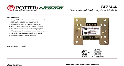
Installation Manual CIZM 4 Conventional Initiating Zone Module 01.11 2011 TO THE INSTALLER manual provides an overview and the installation instructions for the CIZM 4 module This module is only with addressable fire systems that utilize the Potter Nohmi addressable protocol terminals are power limited and should be wired in accordance with the requirements of NFPA 70 NEC NFPA 72 National Fire Alarm Code Failure to follow the wiring diagrams in the following pages will the system to not operate as intended For further information refer to the control panel installation module shall only be installed with listed control panels Refer to the control panel installation manual for system operation Description module CIZM 4 is used to supervise the status of compatible power consuming initiating devices on an Initiating device circuit IDC The CIZM 4 detects an alarm condition and reports to the The module CIZM 4 also supervises the initiating device wiring A A B and B wires and wiring the power supply connected to terminals 24 and 24 to detect an open circuit IDC wiring style is to the NFPA Class B Style B Class A Style D When the module CIZM 4 detects an alarm the is latched until the system reset When the CIZM 4 is used in a Class A mode and an open circuit the module is latched until the system is reset CIZM 4 module has one red LED for local indication of the status of module itself and its wiring Normal are indicated by flashing LED The alarm condition is indicated by constant illumination An open condition is indicated by the lack of the LED operation The system allows maximum 13 points constantly therefore if additional devices are in the alarm condition the LED will flash rather than on steady Setting the Address addressable module smoke sensor heat detector and combination sensor detector must have the set prior connecting the device to the SLC loop The address is set using the hand held device to connecting a device to the SLC loop the following precautions should be taken to prevent potential to SLC or device Verify the following before proceeding Document discrepancies and notify personnel Power in the Addressable Module is removed Field wiring on the module is correctly installed Field wiring has no open or short circuits Wiring diagram 1 Wiring diagram of CIZM 4 in case of Class B Style B 2 Wiring diagram of CIZM 4 in case of Class A Style D SLC wiring style is applicable to the NFPA Class A Style 6 7 Class B Style 4 IDC wiring style is applicable to the NFPA Class B Style B Class A Style D Power supply for terminals 24 and 24 must be power limited SLC loop wiring S S and initiating device wiring A A B and B are power limited Wiring for terminals S S are supervised Wiring for terminals 24 24 A A B B are supervised The jumper JP1 shall be set as Style D when the Class A Style D is required The jumper JP1 shall be set as Style B when the Class B Style B is required Compatible conventional smoke detectors and bases are described in Table 1 All wiring is between 14 2.08 mm2 max and 22 0.32 mm2 min Wire Preparation all wires approximately 1 4 inch from their edges as follows inch 6.4 mm Stripping too much insulation may cause ground fault Stripping too little may cause a poor connection and subsequently an open circuit Installation Instructions 3 Installation into the compatible electrical box Specifications Rated voltage range of SLC input power S S Maximum SLC 24 VDC standby current S S Maximum SLC 24 VDC alarm current S S Operating voltage of external power supply line to 24.0V Output voltage range of IDC A A B B Maximum module standby current of IDC 24 VDC 24 24 Maximum detector standby current of IDC 24 VDC 24 24 2.4mA Maximum module and detector alarm current of IDC 24 to 22.6V in Style B 4.9mA in Style D 24 24 IDC wiring style Maximum wiring resistance of IDC Maximum wiring capacitance of IDC End of line resistor for IDC in NFPA Style B wiring Maximum alarm reset voltage Minimum alarm reset time Operating temperature range Operating humidity range Maximum no of module per loop Dimensions Applicable electrical box for installation Compatibility Identifier A Style D Class B Style B 1 2W V second to 120 0 to 49 to 93 non condensing units H 4.17 W 1.14 D 2 gang box 4 box 1 1 2 box CIZM 4 will only support a single smoke detector in alarm brands of smoke detectors shall not be mixed or matched on any CIZM 4 as this condition has not tested or listed 1 Compatible conventional smoke detectors and bases No approval no No approval no no units units units units units units units units units limit units limit units limit units limit units limit units limit units units