Potter INSTALLATION MANUAL IDC-6 INITIATING DEVICE CIRCUIT EXPANDER

File Preview
Click below to download for free
Click below to download for free
File Data
| Name | potter-installation-manual-idc-6-initiating-device-circuit-expander-3941672508.pdf |
|---|---|
| Type | |
| Size | 1017.95 KB |
| Downloads |
Text Preview
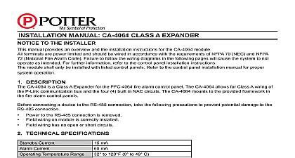
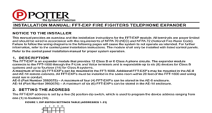
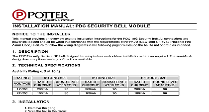
NOTICE TO THE INSTALLER manual provides an overview and the installation instructions for the IDC 6 module terminals are power limited and should be wired in accordance with the requirements of NFPA 70 NEC and NFPA National Fire Alarm Code Failure to follow the wiring diagrams in the following pages will cause the system to not as intended For further information refer to the control panel installation instructions module shall only be installed with listed control panels Refer to the control panel installation manual for proper operation DESCRIPTION Initiating Device Circuit Expander IDC 6 provides an additional 6 inputs per module The panel supports up to 31 IDC 6 modules The circuits are power limited and supervised All inputs are suitable to monitor 2 wire detectors Smoke detectors shall be installed in compliance with NFPA 72 Inputs can also be used for automatic waterflow or supervisory service The IDC 6 communicates via the PLink communication bus The IDC 6 can be in either the control panel cabinet the intelligent power supply AE 2 AE 8 or the AE 14 expander cabinet Each is mounted to the exclusive Stacker Bracket for secure and accessible mounting SETTING THE ADDRESS P Link device has a five 5 position dip switch which is used to program the device address ranging from one 1 thirty one 31 The table below may be used to set dip switches when addressing any P Link module 1 DIP SWITCH SETTINGS TABLE ADDRESSES 1 16 16 16 16 Each gray box indicates that the dip switch is On and each white box indicates Off examples shown below illustrate a P Link dip switch settings the 1st example shows a P Link module not ad where all dip switch settings are in the default Off position the 2nd illustrates an addressed P Link module via dip switch settings 2 EXAMPLES OF P LINK MODuLE SHOWING DEFAuLT DIP SWITCH SETTING uNADDRESSED ADDRESSED 4 4 dip switches are in the Off shows this P Link module 10 Dip switches 2 8 in the On position PAGE 1 OF 5 B 11 17INSTALLATION MANUAL IDC 6 INITIATING DEVICE CIRCUIT EXPANDERPotter Electric Signal Company LLC St Louis MO Phone 800 325 3936 www pottersignal comfirealarmresources com connecting a device to the RS 485 connection take the following precautions to prevent potential damage to the connection Power to the RS 485 connection is removed Field wiring on module is correctly installed Field wiring has no open or short circuits TECHNICAL SPECIFICATIONS Standby Current Alarm Current PWR Standby Current PWR Alarm Current Zone Wiring Resistance Zone Capacitance Zone Short Circuit Current Temperature Range Humidity Range no of IDC 6 Expanders WxHxD mA mA mA maximum Standby mA maximum Alarm ohms max mF max mA to 120 0 to 49 C non condensing x 6 x 1 5 8 IDC PWR can be provided by any fire listed source Power must be 16 VDC 33 VDC and must be power limited INSTALLATION IDC 6 is connected to the fire control panels using a 4 wire RS 485 connection The connection is power limited supervised The IDC 6 must be mounted in either a compatible fire alarm panel the PSN 1000 or within 20 feet of panel or power supply using the AE 2 AE 8 or the AD 14 expander cabinet Each card is mounted to the exclusive Bracket for secure and accessible mounting wiring diagrams shown below illustrate how to wire a IDC 6 as Class B and Class A 3 CLASS B P LINK AND IDC POWER WIRING PAGE 2 OF 5 B 11 17Potter Electric Signal Company LLC St Louis MO Phone 800 325 3936 www pottersignal com INSTALLATION MANUAL IDC 6 INITIATING DEVICE CIRCUIT EXPANDER firealarmresources com 4 CLASS A P LINK AND IDC POWER WIRING 5 EXAMPLE OF WIRING A IDC 6 MODuLE CLASS A LEFT OR CLASS B RIGHT Open Contact Part K EOL Open Contact or Smoke Detector 1 2 3 4 5 6 1 2 3 4 5 6 1 Input 6 are power limited 24 VDC inputs RS 485 wiring style supports class A and class B RS 485 is power limited Wiring for terminals A B and are supervised All wiring is between 12 max And 18 min Wire preparation strip all wires 1 4 inch from their edges as shown here Stripping too much insulation may cause a ground fault Stripping too little may cause a poor connection and subsequently an open circuit inch instructions do not purport to cover all the details or variations in the equipment described nor provide for every contingency to be met in connection with installation operation and maintenance subject to change without prior notification Technical Assistance contact Potter Electric Signal Company at 866 956 1211 performance is based on proper application of the product by a qualified professional further information be desired or should particular problems arise which are not covered sufficiently for the purchaser the matter should be referred to a distributor in your region PAGE 3 OF 5 B 11 17Potter Electric Signal Company LLC St Louis MO Phone 800 325 3936 www pottersignal com INSTALLATION MANUAL IDC 6 INITIATING DEVICE CIRCUIT EXPANDER firealarmresources com 1 COMPATIBLE CONVENTIONAL SMOKE DETECTORS BASES Model MODEL SENSOR BRK MAX NO OF DETECTORS PER ZONE IS 20 SYSTEM MAX NO OF DETECTORS PER ZONE IS 25 MAX NO OF DETECTORS PER ZONE IS 25 MAX NO OF DETECTORS PER ZONE IS 25 MAX NO OF DETECTORS PER ZONE IS 25 OF THE ABOVE FENWAL DETECTORS AND BASES CAN BE USED IN ANY COMBINATION BASE ADAPTOR 70 501000 003 IDENTIFIER MAFE1 FOR SERIES 70 201000 BASES MODELS 001 002 003 AND 005 HOUSING WITH DETECTOR BASE DN 51 IDENTIFIER DH22FE5 FOR CPD 7051 AND PSD 7155 DETECTORS ONLY PAGE 4 OF 5 B 11 17Potter Electric Signal Company LLC St Louis MO Phone 800 325 3936 www pottersignal com INSTALLATION MANUAL IDC 6 INITIATING DEVICE CIRCUIT EXPANDER firealarmresources com MODEL MAX NO OF DETECTORS PER ZONE IS 25 HOCHIKI Model HOCHIKI HOCHIKI HOCHIKI HOCHIKI HOCHIKI HOCHIKI HOCHIKI HOCHIKI HOCHIKI HOCHIKI HOCHIKI HOCHIKI HOCHIKI HOCHIKI HOCHIKI IF USING A MIX OF SYSTEM SENSOR AND OTHER SMOKE DETECTORS A MAXIMUM OF 20 DETECTORS SHALL BE PERMITTED PAGE 5 OF 5 B 11 17Potter Electric Signal Company LLC St Louis MO Phone 800 325 3936 www pottersignal com INSTALLATION MANUAL IDC 6 INITIATING DEVICE CIRCUIT EXPANDER firealarmresources com