Potter Installation Manual PAD100-DUCTR Analog Addressable Duct Detector

File Preview
Click below to download for free
Click below to download for free
File Data
| Name | potter-installation-manual-pad100-ductr-analog-addressable-duct-detector-2679354081.pdf |
|---|---|
| Type | |
| Size | 1.01 MB |
| Downloads |
Text Preview
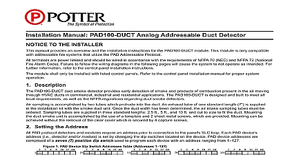
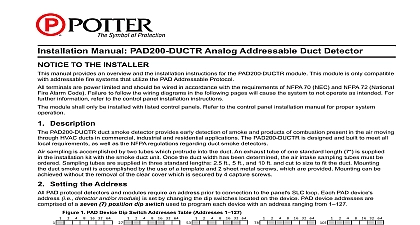
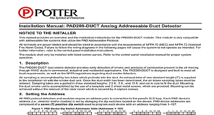
Installation Manual PAD100 DUCTR Analog Addressable Duct Detector TO THE INSTALLER manual provides an overview and the installation instructions for the PAD100 DUCTR module This module is only compatible addressable fire systems that utilize the PAD Addressable Protocol terminals are power limited and should be wired in accordance with the requirements of NFPA 70 NEC and NFPA 72 National Alarm Code Failure to follow the wiring diagrams in the following pages will cause the system to not operate as intended For information refer to the control panel installation instructions module shall only be installed with listed control panels Refer to the control panel installation manual for proper system Description PAD100 DUCTR duct smoke detector provides early detection of smoke and products of combustion present in the air moving HVAC ducts in commercial industrial and residential applications The PAD100 DUCTR is designed and built to meet all requirements as well as the NFPA regulations regarding duct smoke detectors sampling is accomplished by two tubes which protrude into the duct An exhaust tube of one standard length 7 is supplied the installation kit with the smoke duct unit Once the duct width has been determined the air intake sampling tubes must be Sampling tubes are supplied in three standard lengths 2.5 ft 5 ft and 10 ft and cut to size to fit the duct Mounting duct smoke unit is accomplished by the use of a template and 2 sheet metal screws which are provided Mounting can be without the removal of the clear cover which is secured by 4 capture screws Setting the Address PAD protocol detectors and modules require an address prior to connection to the panel SLC loop Each PAD device i e detector and or module is set by changing the dip switches located on the device PAD device addresses are of a seven 7 position dip switch used to program each device with an address ranging from 1 1 PAD Device Dip Switch Addresses Table Addresses 1 16 32 64 16 32 64 16 32 64 16 32 64 16 32 64 16 32 64 16 32 64 Each gray box indicates that the dip switch is On and each white box indicates Off 16 32 64 16 32 64 16 32 64 Electric Signal Company LLC St Louis MO Phone 800 325 3936 www pottersignal com 5406321 A 05 16 PAGE 1 OF 5 examples shown below illustrate a PAD device dip switch settings the 1st example shows a device not addressed where all switch settings are in the default Off position the 2nd illustrates an addressed PAD device via the dip switch settings 2 Examples of PAD Device Showing Default Dip Switch Setting Unaddressed Addressed PAD Device 4 64 4 64 dip switches are in the Off shows this PAD device 42 Dip switches 2 8 are in the On position to the SLC is removed wiring on module is correctly installed wiring has no open or short circuits connecting a device to the SLC loop take the following precautions to prevent potential damage to the SLC or device Technical Specifications Detector Model Voltage Draw Head Model Head Type Test Method Velocity Temperature Material Net Weight Contact Rating Tubes Tube Part Numbers diagnostic test to 4000 ft min to 120 F 0 to 49 C to 85 Relative humidity non condensing backbox clear plastic cover backbox with clear cover 1 2 L x 4 1 2 W x 2 1 4 D lbs 10A 120VAC 10A 250VAC ft 5 ft or 10 ft 1000274 5 1000275 10 1000276 Wiring Diagrams wiring diagrams shown below illustrate how to wire PAD100 DRTS MS RA and MS KA P R devices 3 Example of Wiring a PAD100 DRTS ADDRESSABLE DETECTOR Electric Signal Company LLC St Louis MO Phone 800 325 3936 www pottersignal com 5406321 A 05 16 PAGE 2 OF 5 MANUAL PAD100 DUCTR ANALOG ADDRESSABLE DUCT DETECTORfirealarmresources com 4 Example of Wiring a PAD100 DRTS FACP OR MODULE NEXT MODULE FROM FACP OR MODULE TO FACP OR MODULE PAD100 DRTS C RELAY 250VAC OPTION Keep jumper in position when the PAD100 DRTS full wiring supervision 5 Example of Wiring a MS RA FACP OR MODULE NEXT MODULE FROM FACP OR MODULE TO FACP OR MODULE MS RA RED WIRE MS RA BLACK WIRE C RELAY 250VAC 6 Example of Wiring a MS KA P R FROM FACP OR MODULE TO FACP OR MODULE FACP OR MODULE NEXT MODULE SWITCH LED LED C RELAY 250VAC OPTION IN POSITION Jumper must be position when the MS KA P R OPTION IN POSITION Jumper must be position when the MS KA P R Wire Preparation Strip all wires 1 4 inch from their edges as shown here wiring style supports the Class A Class X and Class B loop wiring and Aux PWR wiring are power limited and supervised wiring is between 12 max and 22 min Stripping too much insulation may cause a ground fault Stripping too little may cause a poor connection and subsequently an open circuit inch Electric Signal Company LLC St Louis MO Phone 800 325 3936 www pottersignal com 5406321 A 05 16 PAGE 3 OF 5 INSTALLATION MANUAL PAD100 DUCTR ANALOG ADDRESSABLE DUCT DETECTORfirealarmresources com Mechanical Installation Instructions PREREQUISITES This guideline contains general information on the PAD100 DUCTR duct smoke detector but does not preclude the NFPA and or ICC documents listed Potter Electric Signal Company assumes no for improperly installed duct detectors To determine the correct installation position for a PAD100 DUCTR duct detector the following factors must be considered A uniform non turbulent laminar airflow between 100 ft min to 4,000 ft min must be present in the HVAC duct To determine velocities examine the engineering specifications that define the expected velocities or use an Alnor model 6000AP meter or equivalent To minimize the impact of air turbulence and stratification on performance a duct smoke detector should be located as far possible downstream from any obstruction i e deflector plates elbows dampers etc In all situations confirmation of and pressure differential within specifications is required pressure differential between the input sampling high pressure tube and exhaust low pressure tube for the PAD100 duct smoke detector should be greater than 0.01 inches of water and less than 1.2 inches of water Identify a code compliant location supply or return side or both for the installation of the duct unit that will permit easy access viewing and serviceability air When installing on the return side install duct units prior to the air being exhausted from the building or diluted with outside When installing duct smoke units downstream of filters fires occurring in the filters will be detected but if the filters become insufficient air flow through the duct unit will prevent the correct operation of the duct detector Duct units installed in supply air side may monitor upstream equipment and or filters Where possible install duct detectors upstream of air humidifiers and downstream of dehumidifiers To prevent false alarms the duct detector should not be mounted in areas of extreme high or low temperatures in areas high humidity exists or in are