Potter Installation Manual PAD100-ZM Zone Module

File Preview
Click below to download for free
Click below to download for free
File Data
| Name | potter-installation-manual-pad100-zm-zone-module-0726851493.pdf |
|---|---|
| Type | |
| Size | 1.04 MB |
| Downloads |
Text Preview
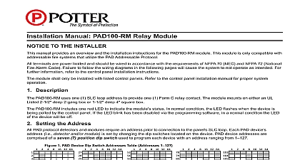
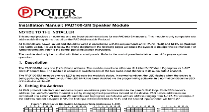
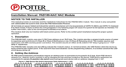
Installation Manual PAD100 ZM Zone Module TO THE INSTALLER manual provides an overview and the installation instructions for the PAD100 ZM module This module is only compatible with fire systems that utilize the PAD Addressable Protocol terminals are power limited and should be wired in accordance with the requirements of NFPA 70 NEC and NFPA 72 National Alarm Code Failure to follow the wiring diagrams in the following pages will cause the system to not operate as intended For information refer to the control panel installation instructions module shall only be installed with listed control panels Refer to the control panel installation manual for proper system Description PAD100 ZM uses one 1 SLC loop address when monitoring two 2 Class B or one 1 Class A circuit The module is used to a zone of conventional 2 wire smoke detectors on an Initiating Device Circuit IDC The module requires and supervises 24VDC auxiliary power connection The 24VDC power source must be either a Potter IPA series addressable panel or a Potter series power supply The IDC may be wired as two individual Class B circuits or one Class A circuit which is selectable by an board DIP switch The module mounts on either an UL Listed 2 1 2 deep 2 gang box or 1 1 2 deep 4 square box PAD100 ZM includes one red LED to indicate the module status In normal condition the LED flashes when the device is polled by the control panel When an input is activated the LED will flash at a fast rate If the LED blink has been disabled the programming software in a normal condition the LED of the device will be off All other conditions remain the same Setting the Address PAD protocol detectors and modules require an address prior to connection to the panel SLC loop Each PAD device i e detector and or module is set by changing the dip switches located on the device PAD device addresses are of a seven 7 position dip switch used to program each device with an address ranging from 1 1 PAD Device Dip Switch Addresses Table Addresses 1 16 32 64 16 32 64 16 32 64 16 32 64 16 32 64 16 32 64 Each gray box indicates that the dip switch is On and each white box indicates Off 16 32 64 examples shown below illustrate a PAD device dip switch settings the 1st example shows a device not addressed where all switch settings are in the default Off position the 2nd illustrates an addressed PAD device via the dip switch settings 2 Examples of PAD Device Showing Default Dip Switch Setting Unaddressed Addressed PAD Device 16 32 64 16 32 64 16 32 64 4 64 4 64 dip switches are in the Off shows this PAD device 42 Dip switches 2 8 are in the On position Electric Signal Company LLC St Louis MO Phone 800 325 3936 www pottersignal com 5406308 A 02 16 PAGE 1 OF 4 the PAD100 ZM is used to monitor two individual Class B circuits a single device address is assigned each input is then as a sub point of the module address For example if the address number is assigned as 8 the B1 input will be 8.1 the B2 input will be 8.2 connecting a device to the SLC loop take the following precautions to prevent potential damage to the SLC or device Technical Specifications to the SLC is removed wiring on module is correctly installed wiring has no open or short circuits Voltage SLC Standby Current SLC Alarm Current Power Required Detector Standby Current of IDC at 24 VDC Module Alarm Current of IDC at 24 VDC Wiring Resistance of IDC Wiring Capacitance of IDC Detector Compatibility Identifier Resistor Temperature Range Humidity Range no of Module Per Loop Options Weight A A 28V to 120 F 0 to 49 C to 93 non condensing units L x 4.17 W x 1.14 D Listed 2 1 2 deep 2 gang box or deep 4 square box lbs Wiring Diagrams wiring diagrams shown below illustrate how to wire a PAD100 ZM module as Class A and Class B Additionally an installation shows how to install the module using a compatible electrical box 3 Example of Installing a PAD100 ZM Using a Compatible Electrical Box Electric Signal Company LLC St Louis MO Phone 800 325 3936 www pottersignal com 5406308 A 02 16 PAGE 2 OF 4 MANUAL PAD100 ZM ZONE MODULEfirealarmresources com 4 Example of Wiring a PAD100 ZM as Class A 5 Example of Wiring a PAD100 ZM as Class B FACP OR MODULE NEXT MODULE FACP OR MODULE NEXT MODULE THE DIP SWITCH POSITION CLASS A WIRING RESISTOR NOT REQUIRED VOLT POWER FROM FACP PREVIOUS MODULE VOLT POWER TO FACP NEXT MODULE THE DIP SWITCH POSITION CLASS B WIRING RESISTOR OHM W 3005013 RESISTOR OHM W 3005013 24 VOLT POWER FACP wiring style supports the Class A Class B and Class X wiring style supports Class A and Class B loop wiring SLC SLC and initiating device wiring B1 B2 and A1 are power limited Wiring for terminals SLC SLC are supervised Wiring for terminals PWR are supervised Wiring for terminals B1 B2 and A1 are supervised Wire Preparation Strip all wires 1 4 inch from their edges as shown here wiring is between 12 max and 22 min inch Stripping too much insulation may cause a ground fault Stripping too little may cause a poor connection and subsequently an open circuit instructions do not purport to cover all the details or variations in the equipment described nor provide for possible contingency to be met in connection with installation operation and maintenance subject to change without prior notification Technical Assistance contact Potter Electric Signal Company at 866 956 1211 performance is based on proper application of the product by a qualified professional further information be desired or should particular problems arise which are not covered sufficiently for purchaser purpose the matter should be referred to a distributor in your region Electric Signal Company LLC St Louis MO Phone 800 325 3936 www pottersignal com 5406308 A 02 16 PAGE 3 OF 4 INSTALLATION MANUAL PAD100 ZM ZONE MODULEfirealarmresources com 1 Compatible Conventional Smoke Detectors Bases Model Model Sensor Brk Max No Of Detectors Per Zone is 10 System Max No Of Detectors Per Zone is 11 Max No Of Detectors Per Zone is 20 Max No Of Detectors Per Zone is 20 Max No Of Detectors Per Zone is 14 Max No Of Detectors Per Zone is 25 HOCHIKI HOCHIKI HOCHIKI