Potter INSTALLATION MANUAL SB-24 SWITCHBOARD

File Preview
Click below to download for free
Click below to download for free
File Data
| Name | potter-installation-manual-sb-24-switchboard-4625807193.pdf |
|---|---|
| Type | |
| Size | 763.76 KB |
| Downloads |
Text Preview
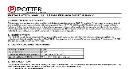
NOTICE TO THE INSTALLER manual provides an overview and the installation instructions for the SB 24 module All terminals are power limited should be wired in accordance with the requirements of NFPA 70 NEC and NFPA 72 National Fire Alarm Code to follow the wiring diagrams in the following pages will cause the system to not operate as intended For further refer to the control panel installation instructions The module shall only be installed with listed control panels to the control panel installation manual for proper system operation DESCRIPTION SB 24 switch board provides 24 programmable push buttons for zone assignment Each button has two LEDs to indicate activity and trouble conditions The SB 24 is equipped with a bracket for secure mounting maximum of 4 SB 24 can be installed within an IPA 4000V TECHNICAL SPECIFICATIONS Current Current Temperature Range Humidity Range mA mA to 120 F 0 to 49 to 93 non condensing INSTALLATION SB 24 connects to the SB 8 through a 10 pin ribbon cable The connections are power limited and supervised The is equipped with bracket to securely mount to the IPA 4000V and LOC 1000 dead front 1 SB 24 INSTALLATION PAGE 1 OF 1 A 3 21INSTALLATION MANUAL SB 24 SWITCHBOARDPotter Electric Signal Company LLC St Louis MO Phone 800 325 3936 www pottersignal comfirealarmresources com