Potter Installation Manual TRM-4 Twin Relay Module

File Preview
Click below to download for free
Click below to download for free
File Data
| Name | potter-installation-manual-trm-4-twin-relay-module-5320691784.pdf |
|---|---|
| Type | |
| Size | 649.74 KB |
| Downloads |
Text Preview
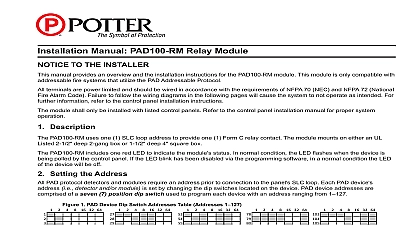
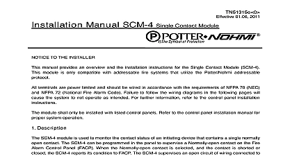
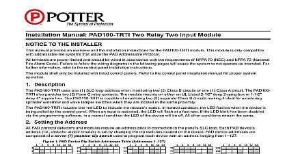
TN51317e 0 01.06 2011 Manual TRM 4 Twin Relay Module TO THE INSTALLER manual provides an overview and the installation instructions for the Twin Relay Module TRM 4 This is only compatible with addressable fire systems that utilize the Potter Nohmi addressable protocol loop wiring signal line circuit is power limited The wiring connecting the contact output terminal NO1 NC1 NO2 C2 NC2 to the controlled device is power limited when the power supply is power limited All should be wired in accordance with the requirements of NFPA 70 NEC and NFPA 72 National Fire Code Failure to follow the wiring diagrams in the following pages will cause the system to not operate intended For further information refer to the control panel installation instructions module shall only be installed with listed control panels Refer to the control panel installation manual for system operation Description TRM 4 module has two Form C relay contact that can be programmed to activate when mapped devices active conditions Those two Form C relay contacts shall activate simultaneously The relay condition C1 and NO1 and C2 and NO2 is Normally open connection and the condition between C1 and NC1 C2 and NC2 is Normally close connection When the TRM 4 receives the command to operate the relay TRM 4 will connect the C1 to NO1 and C2 to NO2 and disconnect the C1 from NC1 and C2 from employs one red LED to indicate the status In normal condition the LED flashes When the relay is activated the LED will turn on constantly The system allows maximum 13 points illuminating therefore if additional devices are in the alarm condition the LED will flash rather than latch on Setting the Address addressable module smoke sensor heat detector and combination sensor detector must have the set prior connecting the device to the SLC loop The address is set using the hand held device to connecting a device to the SLC loop the following precautions should be taken to prevent potential to SLC or device Verify the following before proceeding Document discrepancies and notify personnel Power in the Addressable Module is removed Field wiring on the module is correctly installed Field wiring has no open or short circuits Wiring diagram 1 Wiring diagram of TRM 4 connecting to the relay connection s of the TRM 4 connect the module to the SLC loop and reset it the FACP This is necessary to ensure that the internal relay is unlatched Connection of the module with relay in the latched state terminal between NO1 and C1 and NO2 and C2 are short will activate the device possibly causing damage SLC wiring style is applicable to the NFPA Class A Style 6 7 Class B Style 4 SLC loop wiring S S is power limited Contact output wiring NO1 C1 NC1 NO2 C2 NC2 is power limited when the device power supply power limited Contact output wiring is non power limited when the device power supply is limited Do not mix power limited and non power limited wiring on two contact output using non power limited wiring it must use an alternate opening in the back box and the wire at least 1 4 inches from the SLC wiring Wiring for terminals S S are supervised All wiring is between 14 2.08 mm2 max and 22 0.32 mm2 min Wire Preparation all wires 1 4 inch from their edges as follows inch 6.4 mm Stripping too much insulation may cause ground fault Stripping too little may cause a poor connection and subsequently an open circuit Installation Instructions 2 Installation into compatible electrical box voltage range of SLC input power S S Maximum SLC 24 VDC standby current S S Maximum SLC 24 VDC alarm current S S Output rating resistive output style Operating temperature range Operating humidity range Maximum no of module per loop Applicable electrical box for installation to 24.0V Form C 2 to 120 0 to 49 to 93 non condensing units H 4.17 W 1.14 D 2 gang box 4 box 1 1 2 box to above 3 note instructions do not purport to cover all the details or variations in the equipment described nor provide every possible contingency to be met in connection with installation operation and maintenance subject to change without prior notification Technical Assistance contact Potter Electric Signal Company at 800 325 3936 performance is based on proper application of the product by a qualified professional further information be desired or should particular problems arise which are not covered sufficiently the purchaser s purpose the matter should be referred to Potter Nohmi or a distributor in your region Electric Signal Company LLC Park 370 Place Hazelwood MO 63042 USA 866 956 1211 http www pottersignal com