Potter LTR Residential Low Water Cutoff TacoLTR

File Preview
Click below to download for free
Click below to download for free
File Data
| Name | potter-ltr-residential-low-water-cutoff-tacoltr-8304597612.pdf |
|---|---|
| Type | |
| Size | 1.86 MB |
| Downloads |
Text Preview
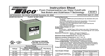
Instruction Sheet Low Water Cutoff Hot Water Boilers June1 2017 UL GUIDE MBPR for Limit Controls per UL Standard 353 Limit Controls UL GUIDE MBPR7 Controls Limit Certified for Canada CSA Standard C22.2 Probe Ratings water only 160 psi 11.2kg cm2 at 250 121 Sensitivity 20K Ohms Extended operation to 40K Ohms Temperature 32 120 0 to 49 Rating NEMA 1 for indoor use only Power 1.5 VA 24 VAC supplied by a Class 2 power source Contact Form B Relay normally closed water detected Models 24VAC Max Load VA 24VAC Switching Model Automatic reset when water level returns to safe Model Press RESET Button when water level returns to safe Integrated test switch for testing safety shutdown each boiler manufacturers specifications for recommended safe water levels a low water condition the Status LED will illuminate RED normal conditions it will illuminate GREEN See Status LED table for details Revision F Dated December 17 2012 G ID 001 3907 Patents 6,904,800 7,243,540 7,317,993 Patents Pending Residential Low Water Cutoff LTR is a microprocessor based water cutoff for detecting the presence to water in a boiler The uses advanced signal processing to identify when the probe levels have decreased due to possible fouling These advanced permit extended operation for probe impedance up to 40K The LTR functions longer without requiring probe cleaning and functions normally under non ideal installation conditions The LTR is for use with hot water boilers and hot water heating boilers Installation must be performed by qualified personnel and in accordance with all national and local codes and ordinances Read all instructions carefully and understand them before starting installation Save instructions for future use Instruct user how to test and operate this cutoff device as described in these instructions Risk of explosion Not for use in hazardous locations Serious injury or death could result The LWCO device must be installed in series ahead of other limit and operating controls installed on the boiler When installations are complete check for correct operation of ALL limit and operating controls For use with hot water boilers and hot water heating boilers only Use on steam boilers could cause improper operation resulting in property damage serious injury and death Shock Hazard Disconnect power source before servicing Serious injury or death could result Use only the wiring harness supplied with the control or factory supplied alternates Use of other wire harness or insulation types could result in fire causing property damage serious injury or death Hot or pressurized boiler systems can discharge steam and hot water Cool boiler system to 80 F 27 C and to 0 psi 0 bar before servicing Failure to do so could result in serious burns Model Pressing the TEST button when water covers the probe will cause the LTR to enter a Low Water Condition Model Pressing the TEST RESET button for two seconds will reset the LTR provided water covers the probe Features LED LED LED Button Connector Button States LED LED LED LED status indicator See LED States table for details LED indicator that service is needed on LTR or system button switch for testing safety shutdown of boiler controls and relay contact connector Reset when pressed after water returns to safe level LED Service LED Contacts Red water level weak probe signal Service soon water condition LW signal too weak LW condition Service now failure Lockout in LW condition power to LWCO Button Pressed in Manual Mode LW condition Install the probe above the minimum safe water level as determined from the boiler manufacturer literature See Fig 1 NOTE This may be in a tapping on the boiler or in the boiler supply or return piping Install the probe to extend into the boiler cavity or piping to make contact with the water Install the probe so that the exposed portion of the stainless steel is a minimum of 1 4 from any grounding surface inside the to prevent the probe from shorting See Fig 2 Hand tighten the LTR into the process connection Do not cross thread Do not use a wrench or other tools to tighten the 1 2 Safe Level Wraps Teflon Do not mount device with probe angled upward or deposits can accumulate on the probe Mount only with probe facing horizontally or vertically downward and maintain 1 4 minimum clearance from electrode and pipe wall Failure to install probe as directed can cause improper operation and damage to equipment and property Apply Teflon tape only to the threads of the LTR Do not use pipe dope or other thread sealants Damage to the control may occur and result in improper operation Hand tighten the LTR into the process connection being careful to not cross thread Do not use a wrench or other tools to tighten the control Damage to the control may occur and result in improper operation 3 for Boilers with Honeywell Aquastat Models L8124E or L8148E or Equivalent Wiring Wiring NPT 1179 1 for Boilers with Honeywell Control Center Model R8285 or Equivalent Shock hazard Disconnect power source before servicing Serious injury or death could result Only use the wiring harness supplied with the control or factory supplied alternates Use of other wire harnesses or insulation types could result in fire causing property damage serious injury and death Instructions Connect the WHITE wire to the C terminal Connect the RED wire to the R terminal Connect the GREEN wire to a ground source that is electrically common to the boiler ground Unplug the factory wired quick connector from the R terminal Plug the male quick connector on the YELLOW wire into the female factory wired quick connector Plug the female quick connector on the yellow wire onto the terminal Shock hazard Disconnect power source before servicing Serious injury or death could result Only use the wiring harness supplied with the control or factory supplied alternates Use of other wire harnesses or insulation types could result in fire causing property damage serious injury and death Instructions Connect the WHITE wire to the Aquastat TV terminal Connect the RED wire to the Aquastat Z terminal Connect the GREEN wire to a ground source that is common to the boiler ground Unplug the factory wired quick connector from terminal Plug the male quick connector on the YELLOW wire into female factory wired quick connector Plug the female quick connector on the YELLOW wire terminal B1 or Wiring VAC Class 2 Systems Models Only VAC VAC Instructions Connect the WHITE wire to the transformer common connection Connect the RED wire to the transformer hot output Connect the GREEN wire to a ground source that is electrically common to the boiler ground Cut off the quick connectors from both YELLOW wires and strip the wire ends Open the connection to the other limit controls ahead of the first limit control Wire the YELLOW leads as shown to connect the LTR relay in series and ahead of all other limit controls