Potter NGP-SPV Self-Purging Valve Kit

File Preview
Click below to download for free
Click below to download for free
File Data
| Name | potter-ngp-spv-self-purging-valve-kit-7025863491.pdf |
|---|---|
| Type | |
| Size | 943.49 KB |
| Downloads |
Text Preview
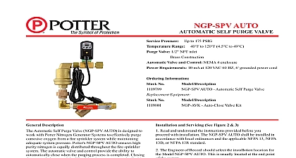
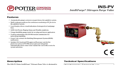
Service Pressure Up to 175 PSIG Range Up to 120 4.5 to 49 Valve 1 2 NPT inlet Brass Construction Information No Potter Nitrogen Self Purge Valve Description Potter Nitrogen Self Purge valve NGP SPV is designed to with Potter Nitrogen Generators Systems to effectively purge oxygen from a fire sprinkler system while maintaining system pressure Potter Self Purge Valve is the easiest way ensure high purity nitrogen is equally distributed throughout the fire system Simply install the NGP SPV off a tee connection the end of the sprinkler system No electrical connections are When the nitrogen generator is in operation the purge orifice bleeds out the oxygen as well as the residual moisture the system The purge valve also provides a sampling port to the nitrogen purity within the system piping the event of an alarm condition the NGP SPV has a built in high water shut off valve that automatically closes when the reaches the vent A plug is supplied to keep the purge orifice of debris when not in use A ball valve allows for isolation of the maintinance of strainer screen replacement of air vent or of the purge orifice and Servicing See Figures 1 2 Read and understand the instructions provided before proceeding installation The NGP SPV shall be installed in accordance with ordinances and the applicable NFPA 13 NFPA 13D or NFPA standard The Engineer of Record should select the Model NGP SPV Potter Self Purge Valve installation location This is usually located the end point of the system The location of the NGP SPV must not interfere with the spray of any sprinkler head valves must be installed in a level horizontal position Figure 2 The piping must be level and arranged in such a manner that water not become trapped Trapped water could cause the NGP SPV to purge Using the union position the purge orifice N2 sampling part for access After installation close ball valve prior to initiating test or purging Purging process operation instructions are located in the Potter Generator Manual The unit should be inspected periodically Thereafter the recommends quarterly or more frequently inspections Inspection should include removal and cleaning of the strainer Remove the screen and flush with clean water Use a wire if necessary to remove any particles trapped in the screen Plug should be installed in orifice when purging process is not performed to keep orifice free of debris and buildup Electric Signal Company LLC St Louis MO Cust Service 866 572 3005 Tech Support 866 956 0988 Canada 888 882 1833 www pottersignal com PAGE 1 OF 2 IN USAMFG 5401520 REV A2 14NGP SPVNITROGEN SELF PURGE VALVEfirealarmresources com 1 NGP SPV Assembly COUPLING VENT VALVE PIPE PLUG WASHER ORIFICE SAMPLING PORT CLOSE NIPPLE UNION CONNECTION CLOSE NIPPLE 90 ELBOW CLOSE NIPPLE STRAINER CLOSE NIPPLE BALL VALVE 2 NGP SPV Installation Diagram FROM SPRINKLER SYSTEM NPT F TEE CONNECTION AND CLOSE NIPPLE BY SPRINKLER CONTRACTOR ORIFICE N2 SAMPLING PORT PLUG INSTALL AFTER COMPLETE PLUG WHEN SAMPLING LEVELS POSITION VENT ORIFCE BALL VALVE IN NORMAL NON PURGE POSITION TEST VALVE shown installed horizontal and level 0400 13 PAGE 2 OF 2 IN USAMFG 5401520 REV A2 14NGP SPVNITROGEN SELF PURGE VALVEfirealarmresources com