Potter OSYSU-CRH Corrosion Resistant Outside Screw and Yoke Valve Supervisory Switch

File Preview
Click below to download for free
Click below to download for free
File Data
| Name | potter-osysu-crh-corrosion-resistant-outside-screw-and-yoke-valve-supervisory-switch-2615074389.pdf |
|---|---|
| Type | |
| Size | 2.16 MB |
| Downloads |
Text Preview
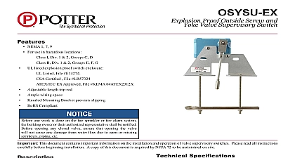
Features NeMa 4X Ip 65 and 6p Ip 67 is 4X For additional corrosion protection of mounting hardware use model OSYSU 2 CRH 40 to 140 40 to 60 operating temperature range Visual switch indicators Two conduit entrances adjustable length trip rod accomodates up to 12aWg wire Three position switch detects tampering and valve closure Knurled mounting bracket prevents slipping Fine adjustment feature for fast easy installation RoHS compliant One or two SpDT contact models 1 2 any work is done on the fire sprinkler or fire alarm system the owner or their authorized representative shall be notified opening any closed valve ensure that opening the valve will not any damage from water flow due to open or missing sprinklers etc OSYSU is used to monitor the open position of an OS Y screw and yoke type gate valve This device is available in models the OSYSU 1 containing one set of SpDT Form C and the OSYSU 2 containing two sets of SpDT Form C These switches mount conveniently to most OS Y valves in size from 2 to 12 50mm to 300mm They will mount some valves as small as 12,5mm cover is held in place by two tamper resistant screws that require special tool to remove The tool is furnished with each device operation of the OSYSU and its associated protective monitoring shall be inspected tested and maintained in accordance all applicable local and national codes and standards and or the Having Jurisdiction manufacturer recommends quarterly more frequently a minimum test shall consist of turning the valve towards the closed position The OSYSU shall operate within first two revolutions of the wheel Fully close the valve and ensure the OSYSU does not restore Fully open the valve and ensure that OSYSU restores to normal only when the valve is fully opened the valve fully to determine that the stem threads do not the switch The switch being activated by the stem threads result in a false valve open indication This document contains important information on the installation and operation of OS Y valve supervisory switches please read all carefully before beginning installation a copy of this document is required by NFpa 72 to be maintained on site Specifications Tamper Fig 8 lbs 0,73 kg Die Cast Finish Red powder Coat Die Cast Finish Black powder Coat parts have corrosion resistant finishes Resistant Screws Cover Tamper Switch available One Set of SpDT Form C Two Sets of SpDT Form C amps at 125 250 VaC amps at 30VDC Resistive mamps minimum at 24 VDC F to 140 40 to 60 4X Ip 65 and NeMa 6p Ip 67 enclosure suitably rated conduit and connector or Outdoor Use See OSYSU eX Bulletin for Hazardous locations Knockouts for 1 2 conduit provided Notice on page 6 and Fig 9 on page 5 13 13D 13R 72 Use subject to change without notice page 1 OF 6 REV G 6 19Potter Electric Signal Company LLC St Louis MO Tech Support 866 956 0988 Customer Service 866 572 3005 www pottersignal comOSYSU SeriesOutside Screw and Yoke Valve Supervisory Switchfirealarmresources com of Operation OSYSU is a 3 position switch The center position is the normal installation position Normal is when the switch is installed on the OS Y valve the is fully open and the trip rod of the OSYSU is in the groove of the valve stem Closing the valve causes the trip rod to ride up out of the groove and the switches Removing the OSYSU from the valve causes the spring to pull the trip rod in the other direction and activates the switches Switch Status Indication are 3 visual indicators to determine the status of the switches 1 the actuator button of the micro switches are on the raised section of the switch actuator 2 the trip rod is perpendicular to the base and lined up with the alignment mark on the mounting bracket 3 the white visual indicator is visible through the window on the back of the switch actuator final test is to meter the contacts marked COM and N O to ensure they are an open circuit when the valve is open and that they close and have continuity 2 revolutions of turning the valve handwheel towards the closed position and the contacts remain closed as the valve is completely closed and until valve is completely opened when the trip rod drops back into the groove in the valve stem 1 2 3 4 5 Rod Locking page 2 OF 6 REV G 6 19Potter Electric Signal Company LLC St Louis MO Tech Support 866 956 0988 Customer Service 866 572 3005 www pottersignal comOSYSU SeriesOutside Screw and Yoke Valve Supervisory Switchfirealarmresources com A 1 1 6 Valve Installation 1 2 Through 2 1 2 Sizes MOUNTING MAY BE USED FINE ADJUSTMENT SWITCH ASSEMBLY MOUNTING BRACKET Valve Installation If the valve stem is pre grooved at 1 8 minimum proceed to step 7 BRACKET Remove and discard e ring and roller from the trip rod With the valve in the FULL OpeN position locate the across the valve yoke as far as possible from the gland so that the spring loaded trip rod of the OSYSU pulled against the non threaded portion of the valve stem the OSYSU with the bracket near the handwheel as in Fig 6 if possible to avoid creating a pinch point the wheel and the OSYSU Loosen the locking screw that holds the trip rod in place and the rod length see Fig 5 When adjusted properly rod should extend past the valve screw but not so far it contacts the clamp bar Tighten the locking screw to in lbs minimum to hold the trip rod in place and properly the enclosure If trip rod length is excessive loosen the locking and remove the trip rod from the trip lever Using break off the one 1 inch long notched section see 10 Reinstall trip rod and repeat Step 3 procedure Mount the OSYSU loosely with the carriage bolts and clamp supplied On valves with limited clearance use J hooks instead of the carriage bolts and clamp bar to mount OSYSU Mark the valve stem at the center of the trip rod Remove the OSYSU Utilizing a 3 16 or 1 4 diameter file file a 1 8 minimum depth groove centered on mark on the valve stem Deburr and smooth the edges the groove to prevent damage to the valve packing and to the trip rod to move easily in and out of the groove as valve is operated a groove depth of up to approximately 3 16 can mounting holes and micro adjustment may be used for fine adjustment of assembly to mounting bracket screws to 20 in lbs minimum it easier to install the OSYSU so that it does not restore it rolls over by the threads of the valve stem Mount the OSYSU on the valve yoke with the spring loaded rod of the OSYSU pulled against the valve stem and in the groove of the stem If possible position the with the flat side of the bracket toward the hand as shown in Fig 6 to help avoid creating a pinch between the wheel and OSYSU When in this preferred position it is usually best to use the white indicator through the window as illustrated in Fig 3 to aid in locating the OSYSU in the correct position on the If the unit must be installed inverted with the white no longer easily visible use the visual indicators the actuator buttons on the micro switches as illustrated Fig 1 or the trip rod alignment mark on the bracket as in Fig 2 to aid in initially locating the OSYSU Final adjustment can be made by slightly loosening the two on the bracket and using the fine adjustment feature Fig 5 The adjustment is correct when the plungers the switches are depressed by the actuator and there is continuity between the COM and NO terminals on the Tighten the adjustment screws and all mounting hardware 20 in lbs minimum Check to insure that the rod out of the groove easily and that the switches activate two turns when the valve is operated from the FULL towards the CLOSeD position Reinstall the cover and tighten the cover screws to 15 in lbs to properly seal the enclosure the valve fully to determine that the stem threads do not the switch The sw