Potter PAAR-B Automatic Air Release with Drip Pan

File Preview
Click below to download for free
Click below to download for free
File Data
| Name | potter-paar-b-automatic-air-release-with-drip-pan-0762458139.pdf |
|---|---|
| Type | |
| Size | 1.26 MB |
| Downloads |
Text Preview
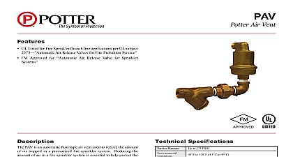
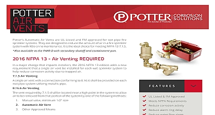
Features UL Listed for Fire Sprinkler Branch line applications per UL subject Air Release Valves for Fire Protection Service FM Approved for Air Release Valve for Sprinkler Provides water retention pan and secondary positive stop shutoff eliminating any possibility of water discharge Specifications Pressure to 175 PSIG Use Only 40 to 120 4.5 to 49 Potter Air Shutoff NPT inlet Orifice Listed Approved Construction indicated by red pop up tab on the shutoff valve set of NC contacts rated 24V AC DC at 2A contacts upon activation of shutoff valve and 6 Lg wiring harness for supervision of shutoff valve valve supervisory switch Model RBVS Supervisory switch Used to monitor the position of the isolation valve subject to change without notice PAAR B is an automatic float type air vent used to reduce the of air trapped in a pressurized fire sprinkler system Reducing amount of air in a fire sprinkler system is essential to help protect system piping from the effects of corrosion that is often found at air water interface in the fire sprinkler system piping as much air as possible will also have a positive effect on performance of vane type waterflow detectors The operation of type waterflow detectors can be delayed or prevented if too much is trapped in the system piping intent of the product is to vent as much air from the fire sprinkler as possible The PAAR B provides automatic venting of air as system is being filled Furthermore trapped air can also be vented the air in the system migrates to the vent location over time The air will automatically close when water reaches the vent piping from the air vent valve is piped to a shutoff valve in a water retention pan The pan retains any inadvertent that may discharge during the venting process If failure of air vent occurs discharged water will reach a specified depth in pan approximately 1 and a water soluble fiber element in the valve dissolves and closes the valve preventing further water The shutoff valve has a visual indication of operation and single set of NC contacts rated 24V AC DC 2A for electronic Recommended The shutoff valve is a single use device contains no user serviceable parts PAAR B provides a 1 2 NPT connection in the bottom of the pan can be used to pipe to a drain page 1 OF 4 Automatic Air Release5401164 REV D 2 19Potter Electric Signal Company LLC St Louis MO Phone 800 325 3936 www pottersignal comfirealarmresources com It is strongly recommended to install a ball valve in line with PAV to assist in servicing the strainer without disabling the system The PAAR B Automatic Shut off valve should be supervised connected to the building fire alarm or to the PSTA After of operation the control valve should be closed and closed until replacement parts are installed Read and understand the instructions provided before you proceed installation The PAAR B shall be installed in accordance local ordinances and the applicable NFPA13 NFPA13D or standard The Engineer of Record should select the Model PAAR B Potter Air Release installation location Usually at a point in system that will vent the most air The location of the PAAR B must not interfere with the spray of any sprinkler head The connection point must be off top of the pipe See Fig 2 the PAAR B in a level position at the recommended location the sprinkler system Use 3 8 threaded rod hangers thru the holes provided in the flange of the pan for additional support there are concerns about inadvertent water damage remove the NPT plug from the bottom of the water retention pan and piping connection to drain For supervision of the shutoff valve activation remove and the fuse cover from the shutoff valve terminals Connect supplied 6 wiring harness connectors to the shutoff valve and make appropriate connections to the fire alarm or local annunciator Model PSTA ordered separately in an junction box An of line resistor EOLR must be according to the wiring diagram in Fig 1 of the PAAR B should be performed after installation filling of the sprinkler system and periodically thereafter in with the applicable NFPA codes and standards and the authority having jurisdiction manufacturer recommends or more frequently Inspection shall include checking for activation of the shutoff indicated by the red pop up tab and checking for blockage in strainer before the air vent and in the cap screen on the outlet Remove the screens and flush with clean water Use a wire to remove any particles trapped in the screens if necessary and Shutoff Valve Replacement inspection reveals activation of the shutoff valve indicated by a red tab on the shutoff valve the air vent valve has failed and must replaced The shutoff valve is a single use device that can not be or repaired and must be replaced Close the ball valve installed between the PAAR B and the system the automatic shutoff valve is electrically supervised disconnect electrical connections from the automatic shutoff valve Remove the pan drain plug from the bottom of water retention and carefully drain any water that may have collected in bottom of the pan Reinstall the plug using teflon tape or pipe sealant Disconnect the 1 2 union in the piping between the PAAR B and automatic shutoff valve from the retention pan Loosen the two screws from vent clamp disconnect any hanger and remove the pan from the vent Disconnect the 1 2 union located between the strainer and the and remove the vent Remove the piping from the existing vent reinstall into the vent and reconnect to the union Remove the 1 2 brass piping from the old activated shutoff valve reinstall on the new shutoff valve using teflon tape on all Be sure to match up the piping from the inlet 1 lg elbow close nipple and union and outlet 1 lg nipple close nipple and 4 lg nipple of the old shutoff valve to inlet and outlet of the new shutoff valve Reconnect the pan to the vent using the vent clamp Make sure that pan is square and level reattach any hanger supports Place the shutoff valve into the retention pan and connect with the provided The shutoff vale must be installed straight and in the retention pan Adjust and secure the vent clamp in a that allows the shutoff valve to rest on the spacer bosses into the bottom of the pan Reconnect the wiring following the instructions provided in 2 under Installation Instructions and Fig 1 Remove and clean the strainer screen by rinsing in clean water a wire brush if necessary and reinstall Open the ball valve and check for proper operation of the air vent Inspection of the PAAR B should be performed after installation periodically thereafter in accordance with the applicable codes and standards and or the authority having jurisdiction recommends quarterly or more frequently Inspection shall include checking for activation of the valve indicated by the red Pop up tab and checking for in the strainer before the air vent and in the cap screen the outlet pipe PAGE 2 OF 4 REV D 2 19Potter Electric Signal Company LLC St Louis MO Phone 800 325 3936 www pottersignal comPAAR BPotter Automatic Air Releasefirealarmresources com 1 NUTS 4 X 4 BOX OF LINE RESISTOR EOLR FACP ALARM PANEL OR LOCAL PSTA 1135 1 ZONE Outline Drawing 2 2 PLCS THREADED SUPPORT HOLeS SHUTOFF VALVE CONNECTIONS FOR SUPERVISION OF SHUTOFF NC CONTACT OPENS UPON OF SHUTOFF VALVE POP UP TAB UPON ACTIVATION WATER SHUTOFF VALVE VENT BRASS