Potter PS120 Series Supervisory Pressure Switch for Excess Pressure Systems

File Preview
Click below to download for free
Click below to download for free
File Data
| Name | potter-ps120-series-supervisory-pressure-switch-for-excess-pressure-systems-8745190623.pdf |
|---|---|
| Type | |
| Size | 1.69 MB |
| Downloads |
Text Preview
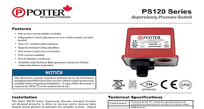
Features One or two switch models available Independent switch adjustment on two switch models no tools Two 1 2 conduit cable entrances Separate isolated wiring chambers Non corrosive pressure connection VdS version available Non Conductive enclosure document contains important information on the installation operation of PS120 pressure switches Please read all instructions before beginning installation A copy of this document is by NFPA 72 to be maintained on site Potter PS120 Series Supervisory Pressure Actuated Switches designed primarily to detect an increase and or decrease from system pressure in automatic fire sprinkler systems Typical are Wet pipe systems with excess pressure pressure air supplies water supplies and monitoring pressure regulators standpipes The PS120 switch is factory set for 120 psi 8,3 bar system pressure The switch marked with the word LOW is set operate at a pressure decrease of 10 psi 0,7 bar at 110 psi 7,6 bar switch marked with the word HIGH is set to operate at a pressure of 10 psi 0,7 bar at 130 psi 9 bar See section heading and Testing if other than factory set point is required Connect the PS120 to the system side of any shutoff or check valve Apply Teflon tape to the threaded male connection on the device not use pipe dope Device should be mounted in the upright position connection down Tighten the device using a wrench on the flats on the device Specifications Entrances Ratings Tamper Adjustment knockouts for 1 2 conduit provided Individual switch and ground screw suitable for dissimilar voltages Form C Amps at 125 250VAC 2.0 Amps at 30VDC SPDT in PS120 1 Two SPDT in PS120 2 incorporates tamper resistant fastener that requires a special for removal One key is supplied with each device 2 lbs at 35 psi 0,14 at 2,41 bar lbs at 225 psi 0,62 at 15,51 bar Weather UV Flame Resistant High Impact Composite Die Cast parts have corrosion resistant finishes F to 140 40 to 60 4 IP66 Rated Enclosure indoor or outdoor when used with 4 conduit fittings operates on decrease at 110 psi 7,6 bar operates in increase at 130 psi 9 bar and on decrease 110 psi 7,6 bar psi 20,68 bar System Connection Nylon 1 2 NPT male Range Use psi 2,41 to 15,51 bar 13 13D 13R 14 72 subject to change without notice PAGE 1 OF 4 SeriesSupervisory Pressure Switch5400933 REV G 2 20Potter Electric Signal Company LLC St Louis MO Phone 800 325 3936 www pottersignal comDRAFT 1firealarmresources com Instructions Remove the tamper resistant screw with the special key Clamping Plate Terminal 2 uninsulated section of a single conductor should not be looped around the and serve as two separate connections The wire must be severed providing supervision of the connection in the event that the wire dislodged from under the terminal Sprinkler Applications 3 PS120 SYSTEM CHECK Y VALVE 926 1A of any shutoff valves between the alarm check valve and the PS10 render the PS10 inoperative To comply with NFPA 72 any such valve be electrically supervised with a supervisory switch such as Potter RBVS Carefully place a screwdriver on the edge of the knockout and apply a force sufficient to dislodge the knockout plug Fig 9 Run wires through an approved conduit connector and affix the to the device A NEMA 4 rated conduit fitting is required outdoor use Connect the wires to the appropriate terminal connections for service intended See Figures 2,4,5 and 6 See Fig 7 for two one conduit wiring and Testing Testing the PS120 may activate other system connected devices use of a Potter BVL see product bulletin 8900067 for details is to facilitate setting and testing of the PS120 pressure switch a BVL bleeder valve is used the pressure to the switch can be and bled from the exhaust port on the BVL without effecting the pressure of the entire system See Fig 3 operation of the pressure alarm switch should be tested upon completion installation and periodically thereafter in accordance with the applicable codes and standards and or the authority having jurisdiction recommends quarterly or more frequently operation point of the PS120 Pressure Switch can be adjusted to point between 35 and 225 psi 2,41 and 15,51 bar by turning the knob s clockwise to raise the actuation point and counter to lower the actuation point In the case of the PS120 2 switches operate independent of each other Each switch may be adjusted to actuate at any point across the switch adjustment Initial adjustment can be made with a visual reference from the top the adjustment knob across to the printed scale on the switch bracket adjustments should be verified with a pressure gauge 1 NPT To prevent leakage apply Teflon tape sealant to male threads only 930 1 PAGE 2 OF 4 REV G 2 20Potter Electric Signal Company LLC St Louis MO Phone 800 325 3936 www pottersignal comPS120 SeriesSupervisory Pressure SwitchDRAFT 1firealarmresources com Connections 4 NORMAL SYSTEM APPLIED LOW 2 CLOSES ON DROP FIRE FIRE 933 1 NORMAL SYSTEM APPLIED TERMINAL WILL CLOSE ON INCREASE Pressure Signal Connection 5 FIRE ALARM PANEL Conduit Wiring 7 out thin section of divider to provide path for wires when wiring switches from one conduit entrance Pressure Signal Connection 6 FIRE ALARM PANEL 928 1 928 4 PRESSURE SWITCH Pressure 8 Pressure Switch PRESSURE SWITCH Pressure Switch PRESSURE SWITCH Common PRESSURE SWITCH 928 2 Closed when installed normal system 930 3 Open when installed normal system Closes on drop Use for pressure signal 930 3 Open when installed normal system Closes on in pressure Use high pressure signal Closed under normal pressure PAGE 3 OF 4 REV G 2 20Potter Electric Signal Company LLC St Louis MO Phone 800 325 3936 www pottersignal comPS120 SeriesSupervisory Pressure Switchfirealarmresources com Knockouts 9 Specifications Type Waterflow Switch type supervisory switches shall be a Model PS120 as by Potter Electric Signal Company St Louis MO and shall installed on the fire sprinkler system as shown and or specified herein shall be provided with a NPT male pressure connection to be into the air supply line on the system side of any shut off valve Model BVL bleeder valve as supplied by Potter Electric Signal Company St Louis MO or equivalent shall be connected in line with the PS120 to a means of testing the operation of the supervisory switch See Fig 3 switch unit shall contain SPDT Form C switch es One switch shall set to operate at a pressure decrease of 10 psi 0,7 bar from normal If switches are provided the second switch shall be set to operate at a increase of 10 psi 0,7 bar from normal contact shall be rated at 10.1 Amps at 125 250VAC and 2.0 Amps 30VDC The units shall have a maximum pressure rating of 300 psi bar and shall be adjustable from 35 to 225 psi 2,41 to 15,51 bar pressure switch shall be UL ULC and CSFM listed FM and approved and NYMEA accepted