Potter PS40-EX Explosion Proof Low High Supervisory Pressure Switch for Dry Valves - Nominal System Pressure 40 psi

File Preview
Click below to download for free
Click below to download for free
File Data
| Name | potter-ps40-ex-explosion-proof-low-high-supervisory-pressure-switch-for-dry-valves-nominal-system-pressure-40-psi-9261784350.pdf |
|---|---|
| Type | |
| Size | 1.29 MB |
| Downloads |
Text Preview
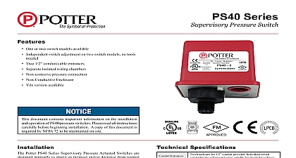
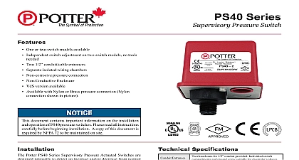
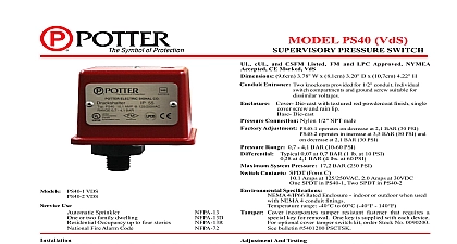
Features Designed and approved for use in hazardous locations Weatherproof Two independently adjustable switches no tools needed Brass pressure connection Solid metal enclosure document contains important information on the installation operation of PS40 EX pressure switches Please read all carefully before beginning installation A copy of this is required by NFPA 72 to be maintained on site Potter PS40 EX Series Supervisory Pressure Actuated Switches are primarily to detect an increase and or decrease from normal pressure in automatic fire sprinkler systems located in hazardous Typical applications are air nitrogen supervision in dry pipe pre action systems pressure tanks air supplies and water supplies PS40 EX has two switches The Low switch is factory set to activate approximately 30 psi 2,1 BAR on a decrease in pressure The High is factory set to activate at approximately 50 psi 3,5 BAR an increase in pressure NFPA 72 requires a supervisory signal if pressure increases or decreases by 10 psi from normal The PS40 factory set for a normal air pressure of 40 psi See section heading and Testing if other than factory set point is required Connect the PS40 to the system side of any shutoff or check Apply teflon tape to the threaded male connection on the Do not use pipe dope Device should be mounted in the upright position Threaded down must be performed by qualified personnel and in accordance with all national and local codes and ordinances hazard Disconnect power source before servicing Serious injury or death could result all instructions carefully and understand them before starting installation Save instructions for future use Failure to read and understand instructions could result in improper operation of device resulting in serious injury or death of explosion Not for use is hazardous locations Serious injury or death could result DEMKO No 03 ATEX 0311298X IECEx UL 18.0005X EN60079 0 2012 A11 2013 EN60079 1 2007 Specifications NPT male brass fitting Dia x 178mm H 6 Dia x 7 H aluminum Setting Range Pressure Contact Entrance Rating Tamper Use switch operates on pressure decrease at 206 BAR 30 PSI switch operates on pressure increase at 344 BAR 50 PSI kPA 69 BAR 10 PSI to 1207 kPA 12.07 BAR 175 kPA 14 BAR 2 PSI at 138 kPA 1.38 BAR 20 PSI kPA 34 BAR 5 PSI at 1207 kPA 12.07 BAR 175 PSI kPA 20.68 BAR 300 PSI Sets of SPDT Form C Amps at 125 250 VAC Amps at 30 VDC NPT female conduit opening maintain type component protection use an Ex conduit sealing device use in hazardous locations classified by CENELEC db IIB T6 Gb I Div 1 Groups B C D II Div 1 Groups E F G III Div 1 4,9 to 60 40 to 140 incorporates tamper resistant fastener that requires special key for removal One key is supplied with each 13 13D 13R 72 PAGE 1 OF 4 Proof Supervisory Pressure Switch5400983 REV JJ 01 18Potter Electric Signal Company LLC St Louis MO Phone Phone 800 325 3936 www pottersignal comfirealarmresources com and Testing Testing the PS40 EX may activate other system connected operation of the pressure supervisory switch should be tested upon of installation and periodically thereafter in accordance with applicable local national and NFPA codes and standards and or the having jurisdiction manufacturer recommends quarterly or frequently use of a Potter BVL see product bulletin 5400799 for details is to facilitate setting and testing of the PS40 EX pressure When a BVL bleeder valve is used the pressure to the switch can isolated and bled from the exhaust port on the BVL without affecting supervisory pressure of the entire system See Fig 2 operation point of the PS40 EX Pressure Switch can be adjusted to point between 69 kPA 69 BAR 10 PSI to 1207 kPA 12.07 BAR 175 by turning the adjustment knob s clockwise to raise the actuation and counter clockwise to lower the actuation point Each switch be independently adjusted to actuate at any point across the switch range If the pressure needs to be adjusted from the factory adjust the system pressure to the desired trip point Use an on the appropriate contact COM and NC for pressure decrease COM and NO for pressure increase Adjust the knurled knob until meter changes state At that point the switch is set for that particular Final adjustments should be made with a pressure gauge position of the top of the adjustment knob across to the printed scale on switch bracket can be used to provide an approximate visual reference the pressure switch setting Conditions For Safe Use of flameproof joints are other than the relevant minimum or specified in Table 2 of EN 60079 1 2007 Pressure switches marked with an and manufacturer drawing no 1350402 detail dimensions of flameproof joints System Supervisory Signal air the PS40 EX to the Dry Pipe Valve Trim piping on the side of any shutoff or check valve in the supervisory Air Gas Pipe Valve supply line connected to the DPV A Model BVL valve as supplied by Potter Electric Signal St Louis MO or shall be connected between the air line and the device to a means of testing the operation of the supervisory switch Air Only To test the High setting the system pressure must be to operate the switch Terminal Connections Plate Terminal 1 I N N I N 923 3 uninsulated section of a single conductor should not be looped the terminal and serve as two separate connections The must be severed thereby providing supervision of the in the event that the wire becomes dislodged from the terminal Sprinkler Applications 2 SUPERVISORY PRESSURE SWITCH LINE PIPE Y 924 1A closing of any shutoff valves between the alarm check valve the PS10 EX will render the PS10 EX inoperative To comply the IBC IFC and NFPA 72 any such valve shall be electrically with a supervisory switch such as Potter Model RBVS PAGE 2 OF 4 Proof Supervisory Pressure Switch5400983 REV JJ 01 18Potter Electric Signal Company LLC St Louis MO Phone Phone 800 325 3936 www pottersignal comfirealarmresources com Electrical Connections 3 Low and High Air on the Same Zone AIR SWITCH AIR SWITCH AIR SWITCH High switch with pressure Low switch with pressure 5924 1 FIRE ALARM PANEL FIRE ALARM PANEL PRESSURE SWITCH PRESSURE SWITCH VIEW WITHOUT COVER NOTE 1 SCREW THESE CONTACTS CLOSE ON A PRESSURE DECREASE THESE CONTACTS CLOSE ON A PRESSURE INCREASE VIEW WITHOUT COVER PRESSURE KNOB NPT FEMALE CONDUIT TO MAINTAIN COMPONENT USE AN EX CONDUIT DEVICE SCREW AND COVER SLEEVE ACCESS TO PRESSURE KNOBS WHEN ARE PRESSURE KNOB NPT MALE 983 2X To prevent leakage apply Teflon tape sealant to male threads only NOTE 2 Switch Termination Switches are shown in standby condition with applied Switch 1 high changes with pressure increase 2 low changes with pressure decrease PAGE 3 OF 4 Proof Supervisory Pressure Switch5400983 REV JJ 01 18Potter Electric Signal Company LLC St Louis MO Phone Phone 800 325 3936 www pottersignal comfirealarmresources com Specifications Type Waterflow Switch CUL Listed FM ATEX Approved and CE Marked pressure switches shall be furnished and installed at the system connection of eac