Potter PS40 Series Low High Supervisory Pressure Switch for Dry Valves - Nominal System Pressure 40 psi EngGerman

File Preview
Click below to download for free
Click below to download for free
File Data
| Name | potter-ps40-series-low-high-supervisory-pressure-switch-for-dry-valves-nominal-system-pressure-40-psi-enggerman-8254601973.pdf |
|---|---|
| Type | |
| Size | 2.00 MB |
| Downloads |
Text Preview
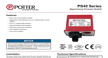
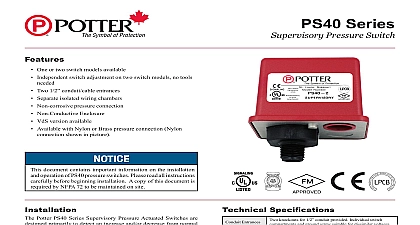
MODEL PS40 VdS PRESSURE SWITCH cUL and CSFM Listed FM and LPC Approved NYMEA CE Marked VdS 9,6cm 3.78 W x 8,1cm 3.20 D x 10,7cm 4.22 H Entrance Two knockouts provided for 1 2 conduit Individual compartments and ground screw suitable for voltages Cover Die cast with textured red powdercoat finish single cover screw and rain lip Connection Nylon 1 2 NPT male Adjustment PS40 1 operates on decrease at 2,1 BAR 30 PSI Base die cast operates in increase at 3,5 BAR 50 PSI and decrease at 2,1 BAR 30 PSI Range 0,7 4,1 BAR 10 60 PSI Typical 0,07 at 0,7 BAR 1 lb at 10 PSI 0,28 at 4,1 BAR 4 lbs at 60 PSI System Pressure 17,2 BAR 250 PSI Contacts SPdT Form C 10.1 Amps at 125 250VAC 2.0 Amps at 30VdC One SPdT in PS40 1 Two SPdT in PS40 2 Specifications 4 IP66 Rated Enclosure indoor or outdoor when used NEMA 4 conduit fittings range 40 to 60 40 140 incorporates tamper resistant fastener that requires a key for removal One key is supplied with each device optional cover tamper switch kit order Stock No 0090200 bulletin 5401200 PSCTSK And Testing operation of the supervisory pressure switch should be tested upon of installation and periodically thereafter in accordance with applicable NFPA codes and standards and or the authority having manufacturer recommends quarterly or more frequently Testing the PS40 may activate other system connected devices use of a Potter BVL see product bulletin 8900067 for details is to facilitate setting and testing of the PS40 pressure switch a BVL bleeder valve is used the pressure to the switch can be and bled from the exhaust port on the BVL without effecting the pressure of the entire system See Fig 3 operation point of the PS40 Pressure Switch can be adjusted to any between 0,7 4,11 BAR 10 and 60 PSI by turning the adjustment clockwise to raise the actuation point and counter clockwise to the actuation point In the case of the PS40 2 both switches operate of each other Each switch may be independently adjusted to at any point acrosss the switch adjustment range Initial adjustment be made with a visual reference from the top of the adjustment knob to the printed scale on the switch bracket Final adjustments should verified with a pressure gauge PS40 1 VdS VdS Use Sprinkler or two family dwelling Occupancy up to four stories Fire Alarm Code Potter PS40 Series Supervisory Pressure Actuated Switches are designed to detect an increase and or decrease from normal system pressure automatic fire sprinkler systems Typical applications are Dry pipe pre action air nitrogen supervision pressure tanks air supplies water supplies The PS40 switch is factory set for 2,8 BAR 40 PSI system pressure The switch marked with the word LOW is set to at a pressure decrease of 7 BAR 10 PSI at 2,1 BAR 30 PSI The marked with the word HIGH is set to operate at a pressure increase 7 BAR 10 PSI at 3,5 BAR 50 PSI See section heading Adjustments Testing if other than factory set point is required Connect the PS40 to the system side of any shutoff or check valve Apply Teflon tape to the threaded male connection on the device do not use pipe dope device should be mounted in the upright position Threaded connection down Tighten the device using a wrench on the flats on the device Instructions Remove the tamper resistant screw with the special key provided Carefully place a screwdriver on the edge of the knockout and sharply apply a force sufficient to dislodge the knockout plug See Fig 9 Run wires through an approved conduit connector and affix the connector to the device A NEMA 4 rated conduit fitting is required for outdoor use Connect the wires to the appropriate terminal connections for the service intended See Figures 2,4,5,6 and 8 Electric Signal Company St Louis MO Customer Service 866 572 3005 Tech Support 866 956 0988 Canada 888 882 1833 www pottersignal com IN USA 5401161 REV d PAGE 1 OF 8 1 NPT PS40 VdS PRESSURE SWITCH Clamping Plate Terminal 2 I N N To prevent leakage apply teflon tape sealant to male threads only of pipe joint cement may result in obstruction of the aperture and loss signal I N 923 3 uninsulated section of a single conductor not be looped around the terminal and as two separate connections The wire be severed thereby providing supervision the connection in the event that the wire dislodged from under the terminal Sprinkler Applications 3 of any shutoff valves between the check valve and the PS10 will render PS10 inoperative To comply with IBC and NFPA 13 any such valve shall be supervised with a supervisory such as Potter Model RBVS Connections 4 NORMAL SYSTEM PRESSURE LOW TERMINAL 2 CLOSES PRESSURE dROP FIRE SUPERVISORY PRESSURE SWITCH LINE PIPE Y 924 1A FIRE NORMAL SYSTEM APPLIED HIGH TERMINAL 1 WILL CLOSE PRESSURE INCREASE IN USA 5401161 REV d PAGE 2 OF 8 PS40 VdS PRESSURE SWITCH Pressure Signal Connection 5 FIRE ALARM PANEL Pressure Signal Connection 6 FIRE ALARM PANEL Conduit Wiring out thin section of divider to provide path for wires when wiring both from one conduit entrance 7 Operation normal system pressure 8 Common Closed when installed under normal system pressure Open when installed under normal system pressure Closes on pressure drop Use for low air signal Open when installed under normal system pressure Closes on increase in pressure Use for high air signal Closed under normal system pressure PRESSURE SWITCH PRESSURE SWITCH Knockouts 9 IN USA 5401161 REV d PAGE 3 OF 8 PS40 VdS PRESSURE SWITCH Installation must be performed by qualified personnel and in accordance with all national and local codes and ordinances Shock hazard Disconnect power source before servicing Serious injury or death could result Read all instructions carefully and understand them before starting installation Save instructions for future use Failure to read and understand instructions could result in improper operation of device resulting in serious injury or death Risk of explosion Not for use is hazardous locations Serious injury or death could result Do not tighten by grasping the switch enclosure Use wrenching flats on the bushing only Failure to install properly could damage the switch and cause improper operation resulting in damage to equipment and property To seal threads apply Teflon tape to male threads only Using joint compounds or cement can obstruct the pressure port inlet and result in improper device operation and damage to equipment Do not over tighten the device standard piping practices apply Do not apply any lubricant to any component of the pressure switch Specifications Pressure Type Waterflow Switch type supervisory switches shall be a Model PS40 as by Potter Electric Signal Company St Louis MO