Potter PTS-C PLUG TYPE SUPERVISORY SWITCH

File Preview
Click below to download for free
Click below to download for free
File Data
| Name | potter-pts-c-plug-type-supervisory-switch-5308916274.pdf |
|---|---|
| Type | |
| Size | 668.64 KB |
| Downloads |
Text Preview
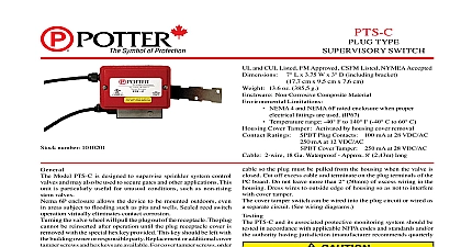
PTS C TYPE SWITCH cm x 9,5 cm x 7,6 cm and cUL Listed FM Approved CSFM Listed NYMEA Accepted 7 L x 3.75 W x 3 D including bracket 13.6 oz 385,5 g Non Corrosive Composite Material Limitations NEMA 4 and NEMA 6P rated enclosure when proper ttings are used IP67 Temperature range 40 F to 140 F 40 C to 60 C Cover Tamper Activated by housing cover removal Ratings SPDT Plug Contacts 100 mA at 28 VDC AC mA at 12 VDC AC Cover Tamper 250 mA at 28 VDC AC 2 wire 18 Ga Waterproof Approx 8 2,43m long Checkout the plug wired to the two P terminals and the plug inserted fully the receptacle place an ohmmeter across the C and N O terminals meter will show Open Unplug the plug from the receptacle The will show continuity The two P terminals will always show continuity when the plug connected regardless of whether the plug is inserted or not cover tamper switch can be wired into the plug circuit or wired as separate circuit See wiring diagrams PTS C and its associated protective monitoring system should be in accordance with applicable NFPA codes and standards and or authority having jurisdiction manufacturer recommends quarterly more frequently sure valve is fully open before restoring PTS C No 1010201 Model PTS C is designed to supervise sprinkler system control and may also be used to secure gates and other applications This is particularly useful for unusual conditions such as non rising valves 6P enclosure allows the device to be mounted outdoors even areas subject to ooding such as pits and wells Sealed reed switch virtually eliminates contact corrosion the valve wheel will pull the plug out of the receptacle The plug be reinserted after operation until the plug receptacle cover is with the special hex key provided This key should be left with building owner or responsible party Replacement or additional cover screws and hex keys are available For cover tamper screws order no 5490344 For hex key order stock no 5250062 plug into housing take the loose end of the cable and loop it the valve handle and into the housing Adjust the length of so the plug must be pulled from the housing when the valve is Cut off excess cable and terminate on the plug terminals of the board Do not leave more than 2 50mm of excess wiring in the Dress wires to outside edge of housing so as not to interfere cover tamper Stipulated By Factory Mutual And Underwriters Laboratories unit is not intended or designed for ordinary use It is a special application device to be used for unusual conditions such as non rising stem valves where no other approved or listed method of protection is available or practical As this unit does not meet NFPA codes and standards restoration signal when the valve is positioned to normal special attention should be given by the responsible parties to assure that the operation of this device is maintained This device should only be restored to normal when the valve is in the normal condition Electric Signal Company LLC 2081 Craig Road St Louis MO 63146 4161 Phone 800 325 3936 Canada 888 882 1833 www pottersignal com IN USA 5401078 REV J 1 OF 2 Installation Stem Valve TYPE SWITCH Diagrams and Cover Tamper Wired To Same Circuit The two P terminals will always show continuity when the plug is connected regardless of whether the plug is inserted or not SINGLE DEVICE MULTIPLE DEVICES And Cover Tamper Wired To Separate Circuits SINGLE DEVICE MULTIPLE DEVICES IN USA 5401078 REV J 2 OF 2