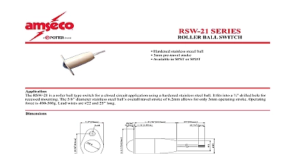
Potter RBVS Retrofit Ball Valve Switch

File Preview
Click below to download for free
Click below to download for free
File Data
| Name | potter-rbvs-retrofit-ball-valve-switch-4690352187.pdf |
|---|---|
| Type | |
| Size | 1.73 MB |
| Downloads |
Text Preview
Features assembled in USa Fits most lever tee type ball valves up to 2 Fits most backflow preventers up to 2 Operates on open or closed valves Includes mounting hardware to supervise coils on most accommodates up to 12 aWg wire Optional field installed cover tamper switch kit 0090224 RoHS compliant any work is done on the fire sprinkler or fire alarm system the owner or their authorized representative shall be notified opening any closed valve ensure that opening the valve will not any damage from water flow due to open or missing sprinklers etc Specifications Large Clamps 6 L x 5 W x 5.3 H 15,2 cm L x cm W x 13,2 cm H Small Clamps 6 L x 4 W x 5.3 H 15,2 cm L x cm W x 13,2 cm H Solenoid Clamp assembly 5.1 L x 3.3 W x 6 13 cm L x 8,38 cm W x 15,24 cm H This document contains important information on the installation and operation of the RBVS Universal Ball Valve Solenoid Coil Supervisory please read all instructions carefully before beginning installation a copy of this document is required by NFpa 72 to be maintained on site Model RBVS is designed to monitor the fully open or closed of a ball valve installed in a sprinkler system as well as monitor position of a coil on a solenoid for a preaction deluge system The will fit on most ball valves installed on back flow preventers and trim lines of dry alarm and deluge sprinkler valves The switch if the ball valve handle is moved from the normal position the switch does not track the position of the handle or ball the ball valve handle is under the RBVS plunger a spring loaded will contact the valve handle When the handle is moved from position this actuator extends to the tripped position and the RBVS change state thereby opening or closing a circuit unit also includes a small bracket and clamp to allow the to mount directly to the nipple on the coil of a solenoid valve plunger of the RBVS is actuated by the stud protruding through the of the coil see Fig 6 If a technician removes the coil from the for testing the RBVS will activate cover tamper switch is available and is activated by the removal of the housing cover If an attempt is made to remove the RBVS by the of the mounting brackets the unit will be set into the tripped by this action RBVS can be mounted to the hex portion of the ball valve or back or to the adjoining pipe via two clamps The RBVS is with three sets of mounting kits to accommodate various pipe valve sizes refer to Table 1 an shaped and offset bracket for the switch enclosure and an extension bracket add to the flexibility of the RBVS See Mounting Diagrams and Operation on following pages incorporates tamper resistant fasteners requires a special key for removal One key supplied with each device For optional cover switch kit order Stock No 0090224 See 5401598 Contact Form C 10.1A at 125 VAC 2A at 30 VDC Resistive 10 mAmps minimum at 24 VDC Cover Tamper 5A at 125 VAC 1mA at 5 VDC min 4 Ip66 for use in hazardous locations suitably rated conduit and connections Knockout for 1 2 conduit connection provided Notice on page 6 Composite Material Tamper to 150 40 to 65 subject to change without notice lbs page 1 OF 6 Ball Valve Solenoid Coil Supervisory Switch5401590 REV A 09 19Potter Electric Signal Company LLC St Louis MO Phone 800 325 3936 www pottersignal comfirealarmresources com kits SMALL 10 32 2 1 2 10 32 STEEL PLATED LARGE X 4 HEX HD ZINC 1 4 1 4 20 SOLENOID 1 Mounting Configurations Size Valve Supervise Open Valves Bag to 3 4 to 19mm Kit 10 32 STEEL PLATED 10 32 1 3 4 BRACKET MOUNTING TAMPERPROFF ONE END 8 32 X 1 2 1 4 20 X 3 4 HEX HD SCReW 1 4 8 32 HEX ZINC PLATED 1 2 Fig 4 5 Fig 1 2 Fig 4 5 Item Number Item xQty xQty Item xQty 2 x2 4 x2 16 17 x2 18 19 Kit Kit Kit 2 x2 2 x2 2 x2 2 x2 6 x2 6 x2 6 x2 6 x2 14 15 14 14 15 14 4 x2 16 17 x2 18 x2 19 x2 4 x2 16 17 x4 18 19 20 x2 4 x2 16 17 x2 18 x2 19 x2 8 x2 9 x2 16 17 x2 18 19 8 x2 9 x2 16 17 x2 18 x2 19 x2 8 x2 9 x2 16 17 x4 18 19 20 x2 8 x2 9 x2 16 17 x2 18 x2 19 x2 14 15 4 x2 16 17 x4 18 x2 19 x2 20 x2 6 x2 14 15 8 x2 9 x2 16 17 x4 18 x2 19 x2 20 x2 2 x2 10 21 12 x2 16 17 x4 18 19 20 x2 to 3 4 to 19mm to 2 to 50mm to 2 to 50mm Solenoid 6 Solenoid Kit page 2 OF 6 REV A 09 19Potter Electric Signal Company LLC St Louis MO Phone 800 325 3936 www pottersignal comRBVSUniversal Ball Valve Solenoid Coil Supervisory Switchfirealarmresources com on Lever Handle Valves Select Clamp Mounting Kit clamps and screws based upon pipe valve see Mounting Configuration Table 1 see page 2 See Fig 1 2 for utilization of extension bracket rubber clamp grippers into clamps see Fig 1 2 screws into mounting clamp vee then place over pipe If using Blue Mounting Kit place washer on screw before into clamp vee Place second clamp vee over the screws from step 3 Then thread nuts onto the screws but do not fully tighten be sure hex nuts properly in clamp vee hex recesses Some installations may require one of the mounting screws to inserted from the bottom of the brackets and then trimmed to the extension bracket to clear See Fig 3 Position clamp vee assembly so that the RBVS actuator will the valve handle approximately 1 from its inside end Fig 1 for approximate location Make sure the top face of the assembly is parallel with the ball valve handle when screws Tighten screws alternately to 30 in lbs minimum of torque necessary for positioning attach bracket extension from the Red to the top clamp vee using X Hex bolt and washer do not fully tighten See Fig 2 If bracket extension is not skip to number 9 Attach bracket mounting to bracket extension using X Hex bolt and washer but do not fully tighten See Fig 2 Skip number 10 if bracket extension is necessary Attach bracket mounting from the Red bag directly to the top See Fig 1 using X Hex bolt and washer but not fully tighten Attach RBVS switch enclosure to bracket mounting slot with tamper resistant screw fr