Potter RD13 Series Residential Riser

File Preview
Click below to download for free
Click below to download for free
File Data
| Name | potter-rd13-series-residential-riser-3680124957.pdf |
|---|---|
| Type | |
| Size | 1.64 MB |
| Downloads |
Text Preview
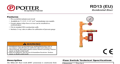
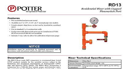
Features Pre assembled and pressure tested Available in 1 1 4 1 1 2 2 nominal pipe size models Female adapter ships loose so riser can be installed in a space Fits in standard 2X4 construction walls Includes 3 way valve to allow for calibration of pressure gauge Installation must be performed by qualified personnel and in accordance with all national and local codes and ordinances Shock hazard Disconnect power source before servicing Serious injury or death could result Risk of explosion Not for use in hazardous locations Serious injury or death could result RD13 Riser with NPT connectors is constructed from Listed products suitable for fire sprinkler services subject to the and installation requirements of Flameguard CPVC pipe Spears CPVC fittings The RD13 Riser incorporates a VSR SG switch gauge and drain test valve The VSR SG flow switch is with union connection to facilitate the installation and removal the switch in confined spaces Using appropriate sealant thread the female adapter on to the water supply Then glue the riser assembly to the female Pipe the drain connection to an adequate drain location of handling the drain discharge The riser can be mounted the horizontal or vertical position Direction of flow is indicated Fig 1 The waterflow switch must be located on the top or the side of the pipe when installed in the horizontal position will prevent debris from entering the throat of the waterflow which could interfere with proper operation Following CPVC manufacturer instructions for preparation and of CPVC piping systems glue the main riser to the main line for the sprinkler heads NOTE All glued connections be completed and cured before the flowswitch is installed Continued on page 2 not over tighten the union nut hand tighten only Use of a may cause damage to the union nut Switch Technical Specifications Pressure Sensitivity for Signal 4 10 GPM 15 38 LPM UL Surge 18 FPS 5.5 m s Fig 2 PSI 12,07 BAR Ratings sets of SPDT Form C Amps at 125 250VAC Amps at 30VDC Resistive m Amps min at 24V DC Resistive range 40 4.5 knockouts provided for 1 2 conduit subject to change without notice Use Sprinkler NFPA 13 or two family dwelling NFPA 13D occupancy up to four stories NFPA 13R Fire Alarm Code NFPA 72 Standard BS9251 PAGE 1 OF 3 REV M 6 20Potter Electric Signal Company LLC St Louis MO Tech Support 866 956 0988 Customer Service 866 572 3005 www pottersignal comRD13Residential Riserfirealarmresources com Continued A thread sealant shall be used in making threaded connections Teflon thread tape is the recommended sealant Some thread sealants other Teflon thread tape contain solvents or other materials that may be damaging to CPVC For other types of thread sealants which have been investigated and confirmed to be Compatible refer to www spearsmfg com Attach gauge to riser Apply Teflon tape to fitting of gauge only See Fig 1 Check to make sure the proper paddle is installed on the switch Paddle size must match the riser pipe size and Tee manufacture the flow switch to the RD13 Riser Verify that the o ring is properly positioned in its groove Hand tighten the nut to the union after the flow switch in the appropriate direction to detect waterflow The paddle must not rub the inside of the Tee or bind in any way The should move freely when operated by hand See Fig 1 NOTE Do not leave switch cover off for an extended period of time The side of flow switch must be perpendicular with the riser piping See Fig 3 frequency of inspection and testing for the Model VSR SG and its associated protective monitoring system should be in accordance with applicable and Standards and or the authority having jurisdiction manufacturer recommends quarterly or more frequently If provided the inspector valve usually located at the end of the most remote branch line should be used for test purposes If there is no remote inspection test connection short length of hose may be connected to the discharge of the 1 drain line valve or if the drain line is connected to a drain such as a slop sink or drain that will sufficiently handle the discharge of the main drain valve The drain valve can be used to test the operation of the VSR SG switch minimum flow of 10 GPM 38 LPM is required to activate this switch An orifice equal to the smallest sprinkler head orifice used in the system shall attached to the drain line for testing purposes VSR SG waterflow switch should provide years of trouble free service The retard and switch assembly are easily field replaceable In the event that either component does not perform properly please order replacement retard switch assembly stock number 1029030 There is no required only periodic testing and inspection prevent accidental water damage all control valves should be shut tight and the system completely drained before waterflow detectors are removed or off electrical power to the detector then disconnect wiring nut on union fitting detector clear of pipe Adjustment delay can be adjusted by rotating the retard adjustment knob from 0 the max setting 60 90 seconds The time delay should be set at the required to prevent false alarms Cover Tamper NOT LEAVE OFF EXTENDED OF TIME so arrow base points direction of 1 Male on Sizes may 1 1 4 1 2 or 2 ater fl paddles have raised lettering that show the pipe size and the TEE they are to be used with The proper paddle must be used paddle must be properly attached and the screw that holds the paddle be securely tightened PAGE 2 OF 3 REV M 6 20Potter Electric Signal Company LLC St Louis MO Tech Support 866 956 0988 Customer Service 866 572 3005 www pottersignal comRD13Residential Riserfirealarmresources com 2 Chart Below E F 3 E F A C A D C D 1 2 Gauge Loose NPT 90.00 90.00 Flow Switch Adaptor Shipped Loose switch must be properly orientated Side of cover must be with the pipe Improper orientation could delay or prevent of waterflow Risers ASSEMBLED DIMENSIONS 1 4 1 2 Number Dimension Dimension C Dimension D Dimension E Dimension F 3 4 1 2 16 3 4 18 1 4 1 4 1 2 3 4 3 8 5 8 3 8 5 8 7 8 1 2 5 8 3 4 1 8 1 2 5 8 Information Information Pipe 1 4 1 2 Riser Riser Riser Riser Number Cover Tamper Switch Kit stock no 0090148 Components Retard Switch Assembly stock no 1029030 Flow Switch and NPT Adapter shipped loose in box Replacement VSR G stock no 1144460 PAGE 3 OF 3 REV M 6 20Potter Electric Signal Company LLC St Louis MO Tech Support 866 956 0988 Customer Service 866 572 3005 www pottersignal comRD13Residential Riserfirealarmresources com