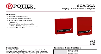
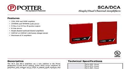
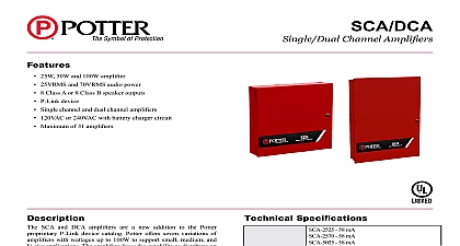
Potter SCA and DCA Single Channel and Dual Channel Amplifier Manual

File Preview
Click below to download for free
Click below to download for free
File Data
| Name | potter-sca-and-dca-single-channel-and-dual-channel-amplifier-manual-8459076123.pdf |
|---|---|
| Type | |
| Size | 5.04 MB |
| Downloads |
Text Preview
SCA and DCA Channel and Dual Amplifier Manual Electric Signal Company LLC Louis MO Service 866 240 1870 Technical Support 866 956 1211 Fax 314 595 6999 listing information visit our website www pottersignal com 5409206 Rev A Installation Wiring Documents 1 SCA 2525 SCA 2570 SCA 5025 and SCA 5070 Wiring Diagram 2 SCA 10070 Wiring Diagram DCA INSTALLATION MANUAL 5409206 REV A 4 21firealarmresources com 3 DCA 5025 and DCA 10025 of Circuit Connection Connection Circuits Type Voltage Voltage Voltage Voltage Voltage Type Limited Limited Limited Limited Limited DCA INSTALLATION MANUAL 5409206 REV A 4 21firealarmresources com Supply Circuit AC terminal is located in the upper left hand portion of the main board The main board supervises the main AC and provides indication that the AC power is absent 4 Main Supply Circuit terminals are rated at 120 VAC 240 VAC 50 60 Hertz and are marked so accordingly on the board The earth connection is marked as and is the furthest connection from the line voltage connection AC input power ratings SCA 2570 SCA 5025 and SCA 5070 Amplifiers of 242mA at the nominal 120 VAC rating of 137mA at the nominal 240 VAC rating Amplifiers of 443mA at the nominal 120 VAC rating of 246mA at the nominal 240 VAC rating and DCA 10025 Amplifiers of 532mA at the nominal 120 VAC rating of 300mA at the nominal 240 VAC rating Battery Circuit battery charging circuit is provided in the bottom portion of the board Terminal connections are provided to wire leads for battery connection The battery must be a recognized or listed sealed lead acid battery or battery charging voltage is approximately 27.3 VDC and the circuit is supervised The battery circuit is protected a non replaceable 7 amp poly switch located on the main circuit board The maximum battery charging circuit is amp DC battery circuit is rated for 8 to 55 AH batteries and the cabinet will house up to two 18 AH batteries The batteries operate the panel for at least 24 hours and 15 minutes of alarm To determine the minimum size batteries for and alarm times desired the installer must complete a battery calculation work sheet to determine the battery size for a particular application For reference the battery calculation work sheet is attached as A Complete standby battery calculations must be completed to ensure adequate battery sizes are provided DCA INSTALLATION MANUAL 5409206 REV A 4 21firealarmresources com V V 593 5 5 Battery Circuit Connections of Circuits Power Limited Non Power Limited High Voltage Wiring main AC power connection is considered high voltage and non power limited The Battery conductors and the AC and trouble relays are nonpower limited All remaining circuits are low voltage power limited connections separation must be maintained between the circuits listed above All separations in the different wiring must be by at least 0.25 inches and the wire insulation must be for the higher voltage the panel there are sufficient knock outs located around the periphery of the cabinet to allow the installer to power limited and non power limited connections SCA and DCA amplifiers operate in conjunction as an expansion device with the IPA 4000V via P Link expansion devices are supervised via the RS 485 connection Wiring is fully supervised and power limited Any to ground of 0 ohms will be annunciated as a ground fault Voltage 24 VDC wire length 6,500 feet wire resistance Maximum wiring resistance is based on load using the following equation P Link Alarm Current x Wire Resistance 6 volts 6 P Link Class B Wiring Example DCA INSTALLATION MANUAL 5409206 REV A 4 21firealarmresources com 7 P Link Class A Wiring Example V Link is a supervised proprietary bus that transmits audio to designated channels on SCA and DCA amplifiers is fully supervised and power limited Any connection to ground of 0 ohms will be annunciated as a ground wire length 6500 feet 8 VM 1000 VLINK1 Class B 9 VM 1000 VLINK1 Class A DCA INSTALLATION MANUAL 5409206 REV A 4 21firealarmresources com 10 VM 1000 VLINK1 and 2 Class B 11 VM 1000 VLINK1 and 2 Class A Specifications SCA 2570 SCA 5025 and SCA 5070 Current Current number of amplifiers Cabinet Dimensions Temperature Range Humidity Range mA mA x 17 x 3 7 8 to 120 F 0 to 49 to 93 non condensing Current Current number of amplifiers Cabinet Dimensions Temperature Range Humidity Range and DCA 10025 Current Current number of amplifiers Cabinet Dimensions Temperature Range Humidity Range mA mA x 17 x 3 7 8 to 120 F 0 to 49 to 93 non condensing mA mA x 27 3 8 x 4 5 8 to 120 F 0 to 49 to 93 non condensing DCA INSTALLATION MANUAL 5409206 REV A 4 21firealarmresources com Wiring Information cabinet has various conduit knockouts located around the cabinet for ease of wire installation In addition this provides a means to separate different types of circuit to reduce electrical interference transient voltage or ratings enclosure requires the use of power limited and non power limited wiring on the main board as well as within the Power limited wiring is to remain separated from non power limited by a minimum or 0.25 inches and all should be insulated to the higher voltage the panel is installed the National Electrical Code NEC NFPA 70 should be followed for the proper and separation of power limited and non power limited circuits The mixing of power limited and non limited should be avoided Refer to the following figure for suggested wiring routing 12 SCA and DCA Wire Routing DCA INSTALLATION MANUAL 5409206 REV A 4 21firealarmresources com Functionality system is completely supervised and is designed to comply with UL 864 and UL 2572 CHANNEL 25W 25V AMPLIFIER CHANNEL 25W 25V OR 70V SELECTABLE AMPLIFIER CHANNEL 50W 25V AMPLIFIER CHANNEL 50W 25V OR 70V SELECTABLE AMPLIFIER CHANNEL 100W 25V OR 70V SELECTABLE AMPLIFIER None CHANNEL 50W 25V AMPLIFIER CHANNEL 100W 25V AMPLIFIER SCA 2525 SCA 2570 SCA 5025 SCA 5070 and SCA 10070 models are addressable single channel amplifiers distribute live voice and ECS to 8 Class A or 8 Class B speaker outputs DCA 5025 and DCA 10025 models are addressable dual channel amplifiers that distribute live voice and ECS to Class A or 8 Class B speaker outputs 13 SCA and DCA Class A and Class B Speaker Wiring maximum of thirty one 31 SCA or DCA amplifiers can be utilized with an IPA 4000V which offers a total of Class B or Class A speaker circuits All speaker circuits are fully supervised and programmable through Potter Reference the IPA 4000V manual for programming instructions DCA INSTALLATION MANUAL 5409206 REV A 4 21firealarmresources com 14 Dip Switch Settings Switch Settings SW 3 SW 4 SW 5 Switch Settings SW 3 SW 4 SW 5 SCA and DCA amplifiers are equipped with a proprietary P Link communication bus to operate in conjunction an IPA 4000V The amplifiers are also equipped with a proprietary V Link bus to receive audio from the VM contained in the IPA 4000V DCA INSTALLATION MANUAL 5409206 REV A 4 21firealarmresources com


