Potter SCV Safe Contact

File Preview
Click below to download for free
Click below to download for free
File Data
| Name | potter-scv-safe-contact-6298540173.pdf |
|---|---|
| Type | |
| Size | 944.34 KB |
| Downloads |
Text Preview
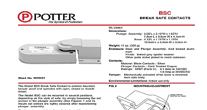
The Model SCV safe contact is UL listed and may be in a variety of ways depending on the type of to be protected different mounting positions are shown in Figs 1 and 3 Ratings 0.1Amp at 130VDC at 30VDC AC INSTRUCTIONS Remove cover screws and cover Remove adjustable plate by removing the two flat screws on the side of the assembly If unit is to be installed as shown in Figs 1 and 2 the contact assembly as shown in Fig 4 Be to reinstall cable clamps as shown 4 REVERSE unit is to be installed as shown in Fig 3 the contact should be as shown in Fig 5 5 NORMAL CONTACT INSTRUCTIONS 1 2 3 Flush Door Only Remove unused extrusion by filing grinding Recessed Doors Adjust the mounting to the proper height The contact can then be located by centering the in the dimple drilled in the frame in Step 4 If the unit is to be mounted with screws see Step 8 the three screw holes with a 27 drill while the unit in place Remove unit and drill the holes with a 33 drill The unit may then be with self tapping 1 4 x 6 32 machine screws The unit may be mounted without the use of screws by an epoxy 7 TO INSTALL ON RAISED DOOR unit may be installed on a raised door by first install a block of the proper height on the frame and follow instructions for flush doors section of and frame Using a 3 8 twist drill make a dimple approximately in depth in the safe frame this should be 1 4 the edge of the door see Fig 6 8 TO INSTALL ON ROUND DOOR unit may be installed on the hinge of some round safes by cutting the head off of one of the hex head bolts putting the dimple in the bolt and mounting device as you would on a flush door 6 section of and frame Electric Signal Company 2081 Craig Road St Louis MO 63146 4161 Phone 800 325 3936 Canada 888 882 1833 www pottersignal com IN USA 8870004 REV E 5400551 12 01 1 OF 2 CONTACT INSTRUCTIONS 9 in position the plunger resting in the dimple it should adjusted so that contacts A and B are open B C and D are closed Contacts E F are tamper contacts and should be open the cover is off When the safe door is contacts A B and C will be closed contacts C and D will be opened If the is depressed too far contacts B and C be open When this contact is used on local alarms or transmitter type Central Station Alarms the ground wire should removed from contact A and folded back under the cable clamp THE SCV the SCV installed the cover on the safe door and the SCV plunger in the dimple of the safe the contacts are Com N C N O normally closed only it is installed in EVD pickup loop it must be wired in before the last device on loop wire from terminal 4 of the EVD C goes to the black of the SCV green wire of the SCV would go to terminal 2 of the shield from terminal 3 of the EVD would connect to white wire then continue to terminal 1 of the EVD P it is wired directly to the relay contacts on the EVD a normally open circuit that shorts on alarm EOL resistor from burglar panel across green white wires white wire to the N O relay contact of the EVD black wire to the N C relay contact of the EVD zone of burglar panel to the common and N O contacts of the EVD See Fig 10 a normally closed circuit that opens on alarm EOL resistor from burglar panel across black white wires white wire to the N O relay contact of the EVD green wire to the common relay contact of the zone of burglar panel to the N O and N C relay of the EVD See Fig 11 10 in position 11 in position IN USA 8870004 REV E 5400551 12 01 2 OF 2