Potter SHB SLB24-75 INDOOR OUTDOOR STROBE HORN STROBE COMBINATION

File Preview
Click below to download for free
Click below to download for free
File Data
| Name | potter-shb-slb24-75-indoor-outdoor-strobe-horn-strobe-combination-0617538492.pdf |
|---|---|
| Type | |
| Size | 834.26 KB |
| Downloads |
Text Preview
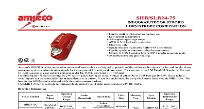
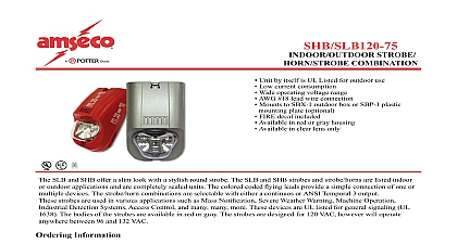
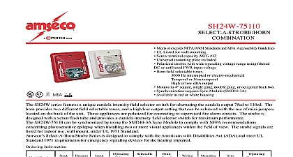
A Brand STROBE COMBINATION Unit by itself is UL Listed for outdoor use Low current consumption Wide operating voltage range AWG 12 18 lead wire connection Clear lens only Synchronization requires the SMD10 3A Sync Module Capable synchronization with other Amseco strobes Mounts to SBX 1 outdoor box or SBP 1 plastic mounting plate Available in red and gray housing SHB SLB indoor and outdoor strobe and horn strobes are designed to provide audible and or visible signals for re and burglar alarm systems and noti cation signals for the purpose of life safety and protection They meet or exceed NFPA ANSI Standards The unit itself is approved as an outdoor appliance under UL 1638 strobe and UL 464 horn SHB SLB24 75 Series operates on 24V system panels having an output voltage of either DC or FWR between 16 33V These audible signals can be connected either independently or in unison It can be synchronized by using the Amseco Sync Module SMD10 3A The for the SHB24 can be silenced while the strobe remains ashing SLB24 75 Series is a high performance high intensity solid state indoor outdoor 24V DC strobe Information Number DC cd VDC VFWR times 150 66 Speci cations indoor outdoor audible and visual alarm indicating appliance shall be Amseco model SHB24 75 or equivalent device The indoor outdoor alarm indicating appliance shall be Amseco model SLB24 75 or equivalent device The horn strobe shall be listed under UL 1971 for signaling devices for the hearing impaired and shall be approved for re protective service The horn strobe and strobe shall be in compliance with UL 1638 Visual Appliance Private Mode Emergency and General Utility for use in indoor outdoor applications The ouptut shall be eld 75cd intensity output The signaling strobe shall operate on 24V DC from a non coded regulated DC supply or recti ed un ltered supply The horn may operate on 24V DC coded system The strobe shall be designed to produce one signal ash second with continuously applied minimum voltage The strobe horn may have a SPC 1 universal back mounting plate capable of wall to a SBX 1 weather proof back box When strobe synchronization is required the strobe horn shall be compatible with the Amseco daisy chain or other source of Amseco sync protocol Audible and visual signaling devices shall be installed in accordance with NFPA guidelines Gang Box Covers Connector Pipe Standard Box Electric Signal Company 2081 Craig Road St Louis MO 63146 4161 Phone 800 325 3936 Canada 888 882 1833 www amseco kai com IN USA MKT 8850019 REV B 1 OF 2 STROBE COMBINATION Brand Diagram 1 and Horn Unison Color 2 Orange 2 White Strobe 2 Red 2 Black 2 and Horn Signal Signal Next or Next or Next or 3 Wiring Diagram for Audible Strobe Class B Circuit without Audible Silence Feature Circuit Module 4 Wiring Diagram for Audible Strobe Class B Circuit with Audible Feature SHB24 Signal Signal Module Next or Next or inches mm Plate 165 85.7 10 Surface Mount Back Box 3.4 31 32 50 5.6 View Plate 16 4.7 View 60 View View RMS Operating Current mA 24V DC 24V FWR Sound Output 10 ft per UL 464 Temporal Output Axis cd cations CAN 525 526 Current mA DC FWR and Strobe typical 145 typical 204 IN USA 8850019 REV B 2 OF 2 22