Potter VSR-AT Auto-Test Waterflow Alarm Switch with Electronic Retard

File Preview
Click below to download for free
Click below to download for free
File Data
| Name | potter-vsr-at-auto-test-waterflow-alarm-switch-with-electronic-retard-6915403827.pdf |
|---|---|
| Type | |
| Size | 1.55 MB |
| Downloads |
Text Preview
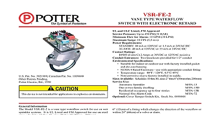
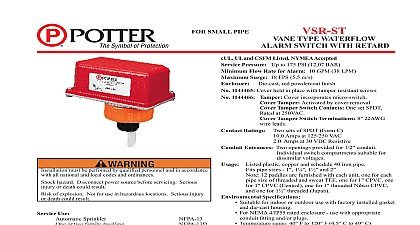
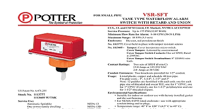
AMP 125 250 VAC 30 VDC CUL FM Approved Pressure 450 PSI 31 BAR UL Sensitivity Range for Signal 4 10 GPM 15 38 LPM UL Surge 18 FPS 5.5 m s Ratings Requirements 24 VDC From Listed or Approved Source Current Draw Entrances Two knockouts provided for 1 2 conduit Specifications NEMA 20 mA 65 mA 120 mA With Battery Backup use with factory installed gasket and die cast housing Temperature Non corrosive Use This document contains important information on the and operation of VSR AT waterflow switches Please read instructions carefully before beginning installation A copy of this is required by NFPA 72 to be maintained on site Installation accordance with all national and local codes and ordinances injury or death could result injury or death could result may result in unintended discharges caused by surges 1 2 1 2 1 2 Information 1 2 PCB Power Supply Ordering Information Supply Battery 8AH 2 REQUIRED Test Switch Ordering Information Zone Test Control Zone Test Control Gang Box Red Gang Box Red Information on wet sprinkler systems It is UL Listed and FM Approved for chart The VSR AT has two sets of alarm contacts and an adjustable recycling electronic retard The alarm contacts are actuated the selected retard time optional auto test Control model ATC 1or ATC 4 or the use of relays and monitor modules as part of a listed addressable Electric Signal Company LLC St Louis MO Phone 866 956 1211 Canada 888 882 1833 www pottersignal com PAGE 1 OF 6 paddle trip stem assembly A successful completion of the auto test auto test detects a problem with the trip stem paddle assembly or if VSR AT switches and retard device are enclosed in a general screws which require a special key for removal IN USAAUTO TEST VSR VSR AT VANE TYPE WATERFLOW ALARM SWITCH WITH ELECTRONIC RETARD AND AUTO TEST FEATUREMFG 5401239 REV C5 15firealarmresources com see Fig 1 cm of a valve or drain the system and drill a hole in the pipe using a hole saw in a slow speed drill see Fig 1 Clean the inside pipe of all growth or other for a distance equal to the pipe diameter on either side of the hole Roll the vane so that it may be inserted into the hole do not bend the chart in Fig 1 The vane must not rub the inside of the pipe or bind in any way not trim the paddle Failure to follow these instructions may prevent device from operating and will void the warranty Do not obstruct or 1 NOT LEAVE COVER OFF FOR EXTENDED PERIOD OF TIME not leave cover off for an extended period of time as leaving the cover could result in damage to the VSR and result in improper operation PAV or similar to exhaust air out of the system and allow the piping to Adjustment delay can be adjusted by turning switch S1 see Fig 6 to the is set at 3 30 second delay The time delay should be set at minimum required to prevent false alarms WATERFLOW must be drilled perpendicular to the pipe and vertically centered WATERFLOW water activates in one direction only 1239 2 MAX 2 5180162 ADAPTERS AS SHOWN ABOVE DN50 ONLY 1146 1F 10 UL 40 UL Wall Thickness Pipe Installation Requirements AT 2 AT 2 1 2 AT 2 1 2 AT 3 AT 3 1 2 AT 4 AT 5 AT 5 AT 6 AT 8 125 062 2.0 125 2.0 PAGE 2 OF 6 IN USAAUTO TEST VSR VSR AT VANE TYPE WATERFLOW ALARM SWITCH WITH ELECTRONIC RETARD AND AUTO TEST FEATUREMFG 5401239 REV C5 15firealarmresour