Potter VSR Series Vane Type Waterflow Alarm Switch with Retard

File Preview
Click below to download for free
Click below to download for free
File Data
| Name | potter-vsr-series-vane-type-waterflow-alarm-switch-with-retard-0485271369.pdf |
|---|---|
| Type | |
| Size | 1.51 MB |
| Downloads |
Text Preview
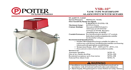
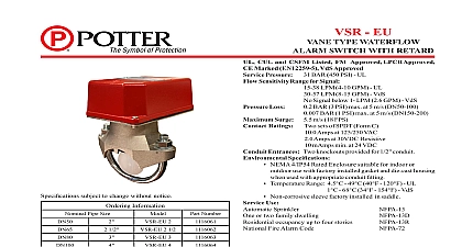
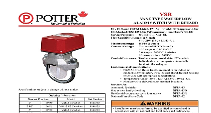
UL CUL and CSFM Listed FM Approved LPCB Approved For Marked EN12259 5 VdS Approved model use VSR EU Pressure 450 PSI 31 BAR UL Sensitivity Range for Signal 4 10 GPM 15 38 LPM UL Surge 18 FPS 5.5 m s Ratings sets of SPDT Form C Amps at 125 250VAC Amps at 30VDC Resistive mAmps min at 24VDC Entrances Two knockouts provided for 1 2 conduit switch compartments suitable dissimilar voltages Specifications NEMA use with factory installed gasket and die cast housing Temperature Non corrosive Use Installation accordance with all national and local codes and ordinances injury or death could result injury or death could result may result in unintended discharges caused by surges Information 1 2 1 2 1 2 1 2 Components This document contains important information on the installation and operation of the waterflow switches Please read all Information chart time necessary to overcome the selected retard period Electric Signal Company LLC St Louis MO Phone 866 956 1211 Canada 888 882 1833 www pottersignal com PAGE 1 OF 4 housing The cover is held in place with two tamper resistant tamper switch is available as an option which may be used for installation instructions of this switch IN USAVSRVANE TYPE WATERFLOWALARM SWITCH WITH RETARDMFG 5401146 REV M11 15firealarmresources com see Fig 1 the system and drill a hole in the pipe using a hole saw in a slow speed drill see Fig 1 Clean the inside pipe of all growth or other for a distance equal to the pipe diameter on either side of the hole Roll the vane so that it may be inserted into the hole do not bend the chart in Fig 1 The vane must not rub the inside of the pipe or bind in any way not trim the paddle Failure to follow these instructions may prevent the device from operating and will void the warranty Do not obstruct or otherwise prevent should disable the alarm system 1 NOT LEAVE COVER OFF FOR EXTENDED PERIOD OF TIME Adjustment delay can be adjusted by rotating the retard adjustment knob from minimum required to prevent false alarms WATERFLOW must be drilled perpendicular to the pipe and vertically centered WATERFLOW water activates in one direction only MAX 2 5180162 ADAPTERS AS SHOWN ABOVE DN50 ONLY 1146 1F 1 2 1 2 1 2 Pipe Installation Requirements Wall Thickness 10 UL 40 UL BS 1387 125 2.0 125 2.0 PAGE 2 OF 4 IN USAMFG 5401146 REV M11 15VSRVANE TYPE WATERFLOWALARM SWITCH WITH RETARDfirealarmresources com 2 3 out thin section of cover when both switches from one conduit 4 Switch Terminal Connections Clamping Terminal 1146 4 not drill into the base as this creates shavings which can create Drilling voids the warranty 5 Typical Electrical Connections The used to operate a local audible or visual annunciator For and warning note Fig 4 uninsulated section of a single conductor should not be looped the terminal and serve as two separate connections The in the event that the wire become dislodged from under terminal Failure to sever the wire may render the device