Potter VSR Series Vane Type Waterflow Alarm Switch with Retard (EU)
File Preview
Click below to download for free
Click below to download for free
File Data
| Name | potter-vsr-series-vane-type-waterflow-alarm-switch-with-retard-eu-1576938420.pdf |
|---|---|
| Type | |
| Size | 2.19 MB |
| Downloads |
Text Preview
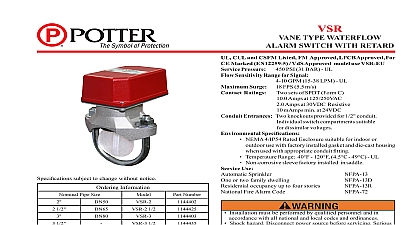
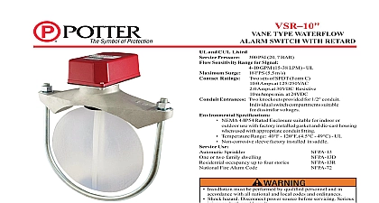
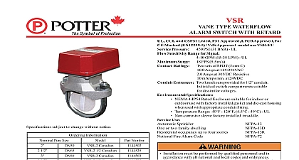
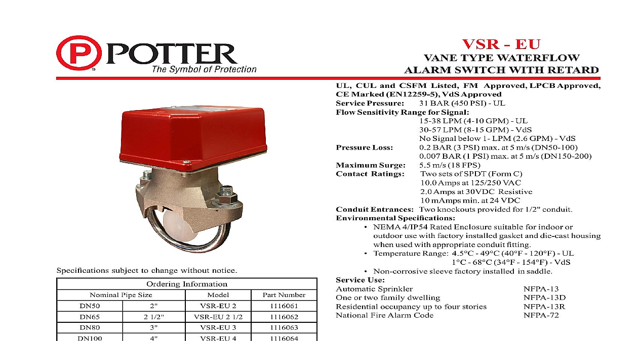
CUL and CSFM Listed FM Approved LPCB Approved Marked EN12259 5 VdS Approved Pressure 31 BAR 450 PSI UL Sensitivity Range for Signal 15 38 LPM 4 10 GPM UL LPM 8 15 GPM VdS Signal below 1 LPM 2.6 GPM VdS Loss BAR 3 PSI max at 5 m s DN50 100 BAR 1 PSI max at 5 m s DN150 200 Surge 5.5 m s 18 FPS Ratings sets of SPDT Form C Amps at 125 250 VAC Amps at 30VDC Resistive mAmps min at 24 VDC Entrances Two knockouts provided for 1 2 conduit Specifications NEMA 4 IP54 Rated Enclosure suitable for indoor or use with factory installed gasket and die cast housing used with appropriate conduit fitting Temperature Range 4.5 49 40 120 UL 68 34 154 VdS Non corrosive sleeve factory installed in saddle Use Sprinkler or two family dwelling occupancy up to four stories Fire Alarm Code Installation must be performed by qualified personnel and in accordance with all national and local codes and ordinances Shock hazard Disconnect power source before servicing Serious injury or death could result Risk of explosion Not for use in hazardous locations Serious injury or death could result switches that are monitoring wet pipe sprinkler systems shall be used as the sole initiating device to discharge AFFF deluge chemical suppression systems Waterflow switches used for this may result in unintended discharges caused by surges air or short retard times subject to change without notice Information Pipe Size 2 2 1 2 3 4 5 6 8 Number 1 2 Components Retard Switch Assembly stock no 1029020 Information Model VSR EU is a vane type waterflow switch for use on wet sprinkler systems It is UL Listed and FM Approved for use on steel pipe 10 through 40 sizes 50 mm thru 200 mm 2 thru 8 LPC approved sizes are 50 mm thru 200 mm 2 thru 8 See Ordering chart VSR EU may also be used as a sectional waterflow detector on large systems The VSR EU contains two single pole double throw snap switches and an adjustable instantly recycling pneumatic retard The switches are actuated when a flow of 38 LPM 10 GPM or more downstream of the device The flow condition must exist for a period of time necessary to overcome the selected retard period VSR EU switches and retard device are enclosed in a general purpose die cast housing The cover is held in place with two tamper resistant which require a special key for removal Electric Signal Company LLC St Louis MO Phone 866 956 1211 Canada 888 882 1833 www pottersignal com PAGE 1 OF 10 IN USAMFG 5401159 REV M 108 12VSR EUVANE TYPE WATERFLOWALARM SWITCH WITH RETARDfirealarmresources com see Fig 1 devices may be mounted on horizontal or vertical pipe On horizontal pipe they shall be installed on the top side of the pipe where they be accessible The device should not be installed within 15 cm 6 of a fitting which changes the direction of the waterflow or within 60 24 of a valve or drain Do not leave cover off for an extended period of time the system and drill a hole in the pipe using a hole saw in a slow speed drill see Fig 1 Clean the inside pipe of all growth or other for a distance equal to the pipe diameter on either side of the hole Roll the vane so that it may be inserted into the hole do not bend crease it Insert the vane so that the arrow on the saddle points in the direction of the waterflow Take care not to damage the non corrosive in the saddle The bushing should fit inside the hole in the pipe Install the saddle strap and tighten nuts alternately to required torque the chart in Fig 1 The vane must not rub the inside of the pipe or bind in any way not trim the paddle Failure to follow these instructions may prevent the device from operating and will void the warranty not obstruct or otherwise prevent the trip stem of the flow switch from moving when water flows as this could damage the flow switch and prevent an alarm an alarm is not desired a qualified technician should disable the alarm system 1 NOT LEAVE COVER FOR AN EXTENDED OF TIME MOUNTING HOLES FOR MINIMAX CARD ADAPTER ONLY DIN 7981 M2,9 X 9,5 MM TAPPING Adjustment delay can be adjusted by rotating the retard adjustment knob from to the max setting 20 30 seconds The time delay should be set at minimum required to prevent false alarms must be drilled perpendicular to the pipe and vertically centered to the Compatible Pipe Installation Requirements chart for size NUTS ON PIPE SO ON SADDLE IN DIRECTION WATERFLOW OF PADDLE IN DIRECTION WATERFLOW water activates in one direction only 1159 1 MAX 2 5180162 ADAPTERS AS SHOWN ABOVE DN50 ONLY 1146 1F Pipe Pipe 2 2 1 2 2 1 2 3 4 5 5 6 8 For copper or plastic pipe use Model VSR CF Pipe Installation Requirements 10 Wall Thickness 40 VDS Size Nuts 2.0 125 062 2.0 125 PAGE 2 OF 10 IN USAMFG 5401159 REV M 108 12VSR EUVANE TYPE WATERFLOWALARM SWITCH WITH RETARDfirealarmresources com 2 remove knockouts Place screwdriver at inside edge of knockouts in the center 3 Switch Terminal Connections Clamping Plate Terminal 1146 4 not drill into the base as this creates metal shavings which can electrical hazards and damage the device Drilling voids the 4 Typical Electrical Connections CAP FROM BREAKER FROM BELL C FROM BREAKER uninsulated section of a single conductor should not be looped around terminal and serve as two separate connections The wire must be thereby providing supervision of the connection in the event that wire become dislodged from under the terminal Failure to sever the may render the device inoperable risking severe property damage loss of life not strip wire beyond 3 8 of length or expose an uninsulated conductor the edge of the terminal block When using stranded wire capture strands under the clamping plate 1 2 3 connecting to a UL Listed panel use the panel valve for circuit supervision 1159 2 The Model VSR EU has two switches one can be used to operate a central station proprietary or remote signaling unit while the other contact is to operate a local audible or visual annunciator A condition of LPC Approval of this product is that the electrical entry must be sealed to exclude moisture For supervised circuits see Terminal Connections drawing and warning note Fig 3 PAGE 3 OF 10 IN USAMFG 5401159 REV M 108 12VSR EUVANE TYPE WATERFLOWALARM SWITCH WITH RETARDfirealarmresources com frequency of inspection and testing for the Model VSR EU and its associated protective monitoring system shall be in accordance with applicable Codes and Standards and or the authority having jurisdiction manufacturer recommends quarterly or more frequently provided the inspector test valve shall always be used for test purposes If there are no provisions for testing the operation of the fl