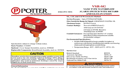
Potter VSR-SFT Waterflow Alarm Switch with Union

File Preview
Click below to download for free
Click below to download for free
File Data
| Name | potter-vsr-sft-waterflow-alarm-switch-with-union-0923465187.pdf |
|---|---|
| Type | |
| Size | 746.90 KB |
| Downloads |
Text Preview
FOR SMALL PIPE TYPE WATERFLOW ALARM WITH RETARD AND UNION UL and CSFM Listed CE Marked NYMEA ACCEPTED Pressure Up to 175 PSI 12,07 BAR Flow Rate for Alarm 8 10 GPM 30 38 LPM Surge 18 FPS 5,5 m s 1113777 Cover held in place with tamper resistant screws 1113605 Tamper Cover incorporates micro switch Tamper Activated by cover removal Tamper Switch Contacts One set SPDT Rated 250VAC Tamper Switch Terminations 8 22AWG wire Die cast red powdercoat nish Ratings Two sets of SPDT Form C Amps at 125 250 VAC Amps at 30 VDC Entrances Two knockouts provided for 1 2 conduit Listed plastic copper and schedule 40 iron pipe pipe sizes 1 1 1 4 1 1 2 and 2 12 paddles are furnished with each unit one for each size of threaded and sweat TEE one for 1 CPVC one 1 CPVC Central one for 1 1 2 polybutylene and one 1 1 2 threaded Japan Speci cations die cast housing Suitable for indoor or outdoor use with factory installed gasket For NEMA 4 IP55 rated enclosure use with appropriate tting and or plugs Temperature range 40 F to 120 F 4,5 C to 49 C This device is not intended for applications in explosive orienting the device in the appropriate direction to detect water ow shown in Fig 2 Do not over tighten the union nut hand tighten only vane must not rub the inside of the TEE or bind in any way The should move freely when operated by hand device can also be used in copper or plastic pipe installations with proper adapters so that the speci ed TEE tting may be installed the pipe run AND TESTING Check the operation of the unit by the inspector test valve at the end of the sprinkler line or the and test connection if an inspector test valve is not provided there are no provisions for testing the operation of the ow detection on the system application of the VSR SFT is not recommended advisable frequency of the inspection and testing and its associated protective system should be in accordance with the applicable NFPA and Standards and or authority having jurisdiction manufacturer quarterly or more frequently 1113605 W TSK Patent No 6,471,255 No 1113777 Use Sprinkler or two family dwelling occupancy up to four stories Fire Alarm Code Model VSR SFT is a vane type water ow switch for use on wet systems that use 1 1 1 4 1 1 2 or 2 pipe sizes It is equipped a union to accommodate installation in con ned spaces unit contains two single pole double throw snap action switches and adjustable instantly recycling pneumatic retard The switches are when a ow of 8 10 gallons per minute 30 38 liters per minute more occurs downstream of the device The ow condition must exist a period of time necessary to overcome the selected retard period These devices may be mounted in horizontal or pipe On horizontal pipe they should be installed on the top of the pipe where they will be accessible The units should not be within 6 15 cm of a valve drain or tting which changes the of the water ow The unit has a 1 NPT tting for threading a non corrosive TEE See Fig 1 for proper TEE size type and Select the proper paddle for the pipe size and type of TEE See Fig 3 for instructions on how to change the paddle the union nut and separate the 1 NPT tting from the VSR Use no more than three wraps of te on tape as thread lubricant the VSR SFT to the 1 NPT tting verifying that the o ring properly positioned in its groove Hand tighten the nut on the union Electric Signal Company 2081 Craig Road St Louis MO 63146 4161 Phone 800 325 3936 Canada 888 882 1833 www pottersignal com IN USA 8800010 REV N 5401063 11 05 PAGE 1 OF 2 SMALL PIPE TYPE WATERFLOW ALARM WITH RETARD AND UNION 2 Adjustment change time turn knob either for desired time delay the minimum amount of retard to prevent false alarms A setting is usually adequate for this set at 3 RETARD SETTINGS IN SEC 1 the tting into the TEE tting as shown sweat TEE no threaded bushings inserts or adapters are unless they comply with the dimensions listed in the below To prevent leakage apply te on tape sealant to the 1 male tting only Do not use any other type of lubricant or the depth to the inside bottom of the TEE should the following dimensions DEPTH REQUIREMENT SIZE x 1 x 1 x 1 1 4 x 1 x 1 1 2 x 1 x 2 x1 are 12 paddles furnished each unit One for each size threaded sweat or plastic TEE described in Fig 1 The paddles raised lettering that show pipe size and type of TEE they are to be used with The paddle must be used The must be properly attached Fig 3 and the screw that the paddle must be securely FIG 4 SWITCH TERMINAL CONNECTIONS CLAMPING PLATE TERMINAL I N N uninsulated section of a single conductor should be looped around the terminal and serve as two connections The wire must be severed providing supervision of the connection in the that the wire becomes dislodged from under the I N 923 3 with optional Cover Switch Kit TAMPER WITH COVER IN 8810018 2 5 TYPICAL ELECTRICAL CONNECTIONS SETS OF NORMALLY CONTACTS ON ALARM ZONE FIRE PANEL FROM PANEL N C AND N O MARKINGS ON SWITCH ARE FOR AN ALARM CONTACTS ARE REVERSED THE DEVICE IS IN THE CONDITION DC HOT AC DC OR AC 761 2 The model VSR SFT has two switches one can be used to a central station proprietary or remote signaling unit the other is used to operate a local audible or visual For supervised circuits see Terminal Connections and caution note Fig 4 WARNING to the possibility of unintended discharges caused by pressure surges trapped air or short retard times water ow switches that are monitoring wet pipe systems should not be used as the sole initiating device to discharge AFFF deluge or chemical suppression systems IN USA 8800010 REV N 5401063 11 05 PAGE 2 OF 2