Potter VSR-SG Waterflow Alarm Switch with Glue-in Union Canadian

File Preview
Click below to download for free
Click below to download for free
File Data
| Name | potter-vsr-sg-waterflow-alarm-switch-with-glue-in-union-canadian-1762409853.pdf |
|---|---|
| Type | |
| Size | 2.12 MB |
| Downloads |
Text Preview
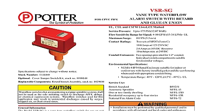
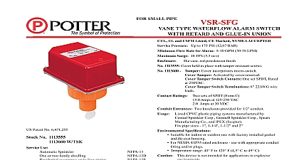
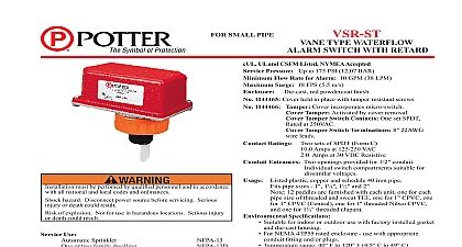
R CPVC PIPE cations subject to change without notice Number 1144461 Cover Tamper Switch Kit stock no 0090148 Components Retard Switch Assembly stock no 1029030 TYPE WATERFLOW SWITCH WITH RETARD GLUE IN UNION CUL and CSFM Listed Pressure Up to 175 PSI 12,07 BAR Sensitivity Range for Signal Surge 18 FPS 5.5 m s Ratings sets of SPDT Form C Amps at 125 250VAC Amps at 30VDC Resistive mAmps min at 24VDC GPM 15 38 LPM UL Entrances Two openings provided for 1 2 conduit switch compartments suitable dissimilar voltages Speci cations NEMA 4 IP54 Rated Enclosure suitable for indoor or use with factory installed gasket and die cast housing used with appropriate conduit tting Temperature Range 40 120 4.5 49 UL Use Sprinkler or two family dwelling occupancy up to four stories Fire Alarm Code Installation must be performed by quali ed personnel and in accordance with all national and local codes and ordinances Shock hazard Disconnect power source before servicing Serious injury or death could result Risk of explosion Not for use in hazardous locations Serious injury or death could result ow switches that are monitoring wet pipe sprinkler systems shall be used as the sole initiating device to discharge AFFF deluge chemical suppression systems Water ow switches used for this may result in unintended discharges caused by surges air or short retard times VSR SG switches and retard device are enclosed in a general die cast housing The cover is held in place with two tamper screws which require a special key for removal A eld cover tamper switch is available as an option which may used to indicate unauthorized removal of the cover See bulletin 5401103 for installation instructions of this switch Information Model VSR SG is a vane type water ow switch for use on wet systems using CPVC plastic ttings manufactured by Tyco Victaulic Ipex and Spears Manufacturing Company that use 1 1 or 2 pipe sizes It is equipped with a union to accommodate in con ned spaces VSR SG contains two single pole double throw snap action and an adjustable instantly recycling pneumatic retard The are actuated when a ow of 10 GPM 38 LPM or more downstream of the device The ow condition must exist for a of time necessary to overcome the selected retard period Electric Signal Company LLC St Louis MO Cust Service 866 572 3005 Tech Support 866 956 0988 Canada 888 882 1833 www pottersignal com IN USA PAGE 1 OF 8 5401190 REV D TYPE WATERFLOW SWITCH WITH RETARD GLUE IN UNION CPVC PIPE see Fig 1 2 and 3 devices may be mounted on horizontal or vertical pipe On horizontal pipe they shall be installed on the top side of the pipe where they be accessible The device should not be installed within 6 15 cm of a tting which changes the direction of the water ow or within 24 cm of a valve or drain The unit has a 1 male tting for gluing into a CPVC plastic tee Do not leave cover off for an extended period of time the union nut and separate the 1 male tting from the VSR SG Glue the 1 male tting into the TEE following the TEE manufacturer for preparation and gluing of CPVC piping systems Note The 1 male tting must bottom out on the stop of the TEE for proper of the VSR SG See Fig 1 Wait 2 to 4 hours to allow the glue to dry before attaching the VSR SG to the 1 male tting Select the proper for the pipe size and type of TEE used See Fig 3 for instructions on how to change paddle Verify that the o ring is properly positioned in groove Hand tighten the nut on the union after orienting the device in the appropriate direction to detect water ow as shown in Fig 2 vane must not rub the inside of the TEE or bind in any way The stem should move freely when operated by hand not trim the paddle Failure to follow these instructions may prevent the from operating and will void the warranty not over tighten the union nut hand tighten only 1 the 1 male tting into the TEE following TEE manufacturer instructions for and gluing of CPVC piping Wait 2 to 4 hours to allow the glue dry before attaching the VSR SG to the 1 tting 2 Adjustment delay can be adjusted by rotating the retard knob from 0 to the max setting 60 seconds The time delay should be set at the required to prevent false alarms COVER TAMPER SWITCH not leave cover off for extended period of time 3 that O ring is in O ring groove before switch paddles are furnished with each unit accommodate the various sizes and of TEES The paddles have lettering that show the pipe size and TEE manufacturer they are to be used The proper paddle must be used The must be properly attached see Fig 3 the screw that holds the paddle must be tightened IN USA water activates in one direction only OF THE TEE BE 1 1 or 2 5401190 REV D PAGE 2 OF 8 SO ARROW BASE POINTS DIRECTION OF MALE ON ALL 1205 1A CPVC PIPE TYPE WATERFLOW SWITCH WITH RETARD GLUE IN UNION 5 Switch Terminal Connections Clamping Plate Terminal 4 out thin section of cover when wiring both switches from one entrance 1205 4 uninsulated section of a single conductor should not be looped the terminal and serve as two separate connections The must be severed thereby providing supervision of the in the event that the wire become dislodged from under terminal Failure to sever the wire may render the device risking severe property damage and loss of life not strip wire beyond 3 8 of length or expose an uninsulated beyond the edge of the terminal block When using wire capture all strands under the clamping plate 6 Typical Electrical Connections The Model VSR SG has two switches one can be used to operate a station proprietary or remote signaling unit while the other is used to operate a local audible or visual annunciator For supervised circuits see Terminal Connections and warning note Fig 5 SOURCE FOR BELL ZONE FIRE PANEL 1146 12 frequency of inspection and testing for the Model VSR SG and its associated protective monitoring system shall be in accordance with applicable Codes and Standards and or the authority having jurisdiction manufacturer recommends quarterly or more frequently provided the inspector test valve shall always be used for test purposes If there are no provisions for testing the operation of the ow detection on the system application of the VSR SG is not recommended or advisable minimum ow of 10 GPM 38 LPM is required to activate this device the person responsible for testing of the fire protection system that this system must be tested in accordance the testing instructions 7 Mounting Dimensions in 89.0 mm in 50.8 mm in 141.2 mm 8 GROUND in mm PADDLE IN USA 1190 1 5401190 REV D 1205 15 1205 15 PAGE 3 OF 8 TYPE WATERFLOW SWITCH WITH RETARD GLUE IN UNION CPVC PIPE detectors monthly If leaks are found replace the detector The VSR SG water ow switch should provide years of trouble free service retard and switch assembly are easily eld replaceable In the unlikely event that either component does not perform properly please order retard switch assembly stock 1029030 see Fig 6 There is no maintenance required only periodic testing an