Potter WFSR-F Pressure Activated Waterflow Alarm Switch with Retard

File Preview
Click below to download for free
Click below to download for free
File Data
| Name | potter-wfsr-f-pressure-activated-waterflow-alarm-switch-with-retard-8420531697.pdf |
|---|---|
| Type | |
| Size | 858.84 KB |
| Downloads |
Text Preview
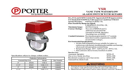
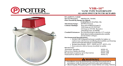
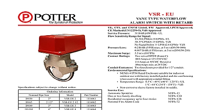
WATERFLOW ALARM SWITCH RETARD H x 8,9cm W x 14,9cm D cUL and CSFM Listed FM Approved and NYMEA CE Marked VdS Approved 5 9 16 H x 3 1 2 W x 5 7 8 D 1.5 lbs 3,3 kg Cover Die cast with textured red powdercoat nish Die cast aluminum Connection 1 2 Male NPT Adjustments adjusted to operate between and 8 PSI 0.35 and 0,55 BAR on pressure system pressure 175 PSI 12,1 BAR Ratings Two Sets of SPDT Form C Amps at 125 250VAC Amps at 30VDC Resistive Entrances Two knockouts provided for 1 2 conduit Speci cations 40 to 120 4,5 to 49 4 Enclosure when used proper conduit ttings or two family dwelling occupancy up to four stories NFPA 13R Fire Alarm Code Use Automatic Sprinkler Cover incorporates tamper resistant fasteners that require special key for removal One key is supplied with each device For cover tamper switch kit order Stock No 0090018 number 1010080 device is not intended for applications explosive environments ow Alarm Switch With Retard For Supervision Of Wet Check Valve Model WFSR F is a pressure operated switch with an adjustable recycling pneumatic retard to prevent false alarms due to water variation The WFSR F is connected into the alarm port of a wet system alarm check valve see WARNING page 2 male NPT pipe tting is provided for connection to the alarm port the alarm check valve No additional mounting or support is required 5 12,7cm to the front of the unit for removal of the cover Install the pressure connection down of the unit is checked by opening the by pass test valve or test valve The frequency of the inspection and testing for the WFSR F and its associated protective monitoring system should in accordance with applicable NFPA Codes and Standards and or having jurisdiction manufacturer recommends quarterly or frequently 1 WFSR F SPRINKLERS 2 Typical Electrical Connections SETS OF NORMALLY CONTACTS ON ALARM ZONE FIRE PANEL FROM PANEL N C AND N O MARKINGS ON SWITCH ARE FOR AN ALARM CONTACTS ARE REVERSED THE DEVICE IS IN THE CONDITION DC HOT AC DC OR AC VALVE WATER 987 1A For supervised circuits see Terminal Connections and caution note Fig 4 Electric Signal Company LLC 2081 Craig Road St Louis MO 63146 4161 Phone 800 325 3936 Canada 888 882 1833 www pottersignal com IN USA 5400987 REV W 761 2 1 OF 2 ALARM SWITCH RETARD 4 Terminal Connections Plate Terminal I N N I N 923 3 uninsulated section of a single conductor not be looped around the terminal and as two separate connections The wire must severed thereby providing supervision of the in the event that the wire becomes from under the terminal 3 NOT LEAVE COVER FOR EXTENDED OF TIME Adjustment change time turn knob either for desired time delay the minimum amount of retard to prevent false alarms a setting is usually adequate for Factory set at 987 30 RETARD SETTINGS IN SEC 5 Typical Wet System te on tape sealant only Apply only male threads of connectors of pipe cement voids warranty as this may obstruct pressure aperture in loss of alarm signal must be installed before any shut valve on alarm port line unless it is by a supervisory switch such Potter Model RBVS system should be tested on a basis or more frequently to proper operation TO 1 RETARD WATER GONG 2 PS10 SWITCH PRESSURE GAUGE PRESSURE PRESSURE GAUGE PRESSURE LINE VALVE TO BUILD EXCESS CONTROL VALVE LINE VALVE BY PASS VALVE 8700023 2A PRESSURE CITY MAINS to the possibility of unintended discharges caused by pressure trapped air or short retard times water ow switches that monitoring wet pipe sprinkler systems shall not be used as sole initiating device to discharge AFFF deluge or chemical systems IN USA 5400987 REV W 2 OF 2