Cerberus Pyrotronics INS-EVI Emergency Voice Interface Modules 9355

File Preview
Click below to download for free
Click below to download for free
File Data
| Name | cerberus-pyrotronics-ins-evi-emergency-voice-interface-modules-9355-5387409126.pdf |
|---|---|
| Type | |
| Size | 1.02 MB |
| Downloads |
Text Preview
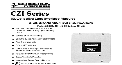
INS EVI Emergency Voice Interface Module AND ARCHITECT SPECIFICATIONS 8 Voice Driver Outputs Isolated Outputs 4 Wire Supervised Connection Interface for CPV 90 or EVACS Multiplex Systems Field Programmable Outputs Mounts on EVK 2 Rail Assembly Output Delay Option Output Bypass Option Operates on the IXL Network Line Listed and ULC Listed FM CSFM and NYMEA Approved INS EVI is a module that provides an interface be a Cerberus Pyrotronics IXL Control Panel and a Pyrotronics CPV 90 Hardwire or Emergency Alarm Communication System Each INS EVI eight outputs which can activate a Model VPM 3 programming matrix located in the voice system VPM 3 provides 10 speaker zone activation inputs INS EVI occupies 2 module spaces on the EVK 2 rail located in the voice system enclosure back The INS EVI is connected to the system Network Line Additional INS EVI modules are to the same circuit Each INS EVI output is through the system control by event logic This allows all speaker matrixing to be field Outputs are isolated and a screw terminal provided to accept an activation source Outputs are VDC a voice module Model VAN 312 is used connection the INS EVI and the VPM 3 is fully supervised INS EVI occupies eight control element addresses and Architect Specifications INS EVI shall provide a fully supervised field program interface between Cerberus Pyrotronics IXL or Panel and the Cerberus Pyrotronics CPV 90 or Emergency Voice Alarm Communication It shall provide eight optically isolated high going which shall be used to activate the Cerberus Model VPM 3 speaker program matrix INS EVI shall occupy two module spaces on the EVK 2 assembly located in the voice system enclosure It shall be connected to the system supervised circuit Each output shall be fully field program via the user laptop computer and activated control by event logic Data Communication Lines all 8 zones enabled per zone enabled all 8 zones enabled per zone enabled NUMBER Diagram Connection Diagram for TB2 DESIGNATIONS TB2 DESIGNATIONS 24 volt TB1 DESIGNATIONS 24 volt return Damage may result from incorrect wiring a VPM 3 and a VAN 312 Supervised Speaker Control are used remove the corresponding zone input from the VPM 3 header HD1 This will supervise connection between the VPM 3 input and the INS EVI 1 activation output 2 activation output 3 activation output 4 activation output 5 activation output 6 activation output 7 activation output 8 activation output EXT Voice 24 volt 24 volt return TB1 DESIGNATIONS 1 activation output 2 activation output 3 activation output 4 activation output 5 activation output 6 activation output 7 activation output 8 activation output 9 activation output 10 activation output The use of other than Cerberus Pyrotronics detectors and bases with Cerberus control equipment will be considered a misapplication of Cerberus Pyrotronics and as such void all warranties either expressed or implied with regards to loss liabilities and or service problems Pyrotronics Ridgedale Ave Knolls NJ 07927 201 267 1300 201 397 7008 in U S A Pyrotronics East Pearce Street Hill Ontario 1B7 CN 905 764 8384 905 731 9182 1994 sheet dated 8 93