Cerberus Pyrotronics RI-B6M Intelligent Initiating Devices Interface Module 6170

File Preview
Click below to download for free
Click below to download for free
File Data
| Name | cerberus-pyrotronics-ri-b6m-intelligent-initiating-devices-interface-module-6170-7683420591.pdf |
|---|---|
| Type | |
| Size | 1.02 MB |
| Downloads |
Text Preview
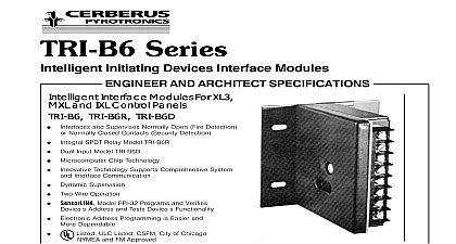
TRI B6M Intelligent Interface Devices Interface Module AND ARCHITECT SPECIFICATIONS Interface Modules For and IXL Control Panels Interfaces and Supervises Normally Open Fire Detection Normally Closed Contacts Security Detection Compact Size Allows Mounting in Single Gang Box Equipment Operates with MXL ALD Loop or IXL ICon Loop Microcomputer Chip Technology Innovative Technology Supports Comprehensive System Interface Communication Dynamic Supervision Two Wire Operation SensorLINK model FPI 32 Programs and Verifies Address and Tests Device Functionality Electronic Address Programming is Easier and Dependable ULC Listed CSFM and NYMEA Pending Pyrotronics TRI B6M Intelligent interface module designed to provide the means of interfacing direct devices to the MXL system ALD loop circuit or IXL system ICon loop circuit Pyrotronics TRI B6M Intelligent interface module the market most advanced method of address and supervision combined with sophisti control panel communication Each TRI B6M module incorporates microcomputer chip and its sophisticated bi directional communi capabilities with the control panel TRI B6M is designed to monitor a normally open or dry contact and reports the contact status to the panel device microcomputer chip has the capacity of in memory identification information as well as operating status information Pyrotronics innovative technology allows all intelligent interface modules to be programmed using the SensorLINK model FPI 32 Programmer Tester FPI 32 Programmer Tester is a compact portable driven accessory that makes programming and an interface device faster easier and more depend than previous methods The FPI 32 eliminates the for mechanical addressing mechanisms such as jumpers DIP switches or rotary dials because it sets the TRI B6M interface address into interface microcomputer chip non volatile memory corrosion and other conditions that deteriorate addressing mechanisms are no longer a for concern This TRI B6M is connected to the with the programming cable provided the tester This cable utilizes two 2 alligator clip to attach to the TRI B6M P N 110 694927 TRI B6 Series has five leads one for grounding which wired to the system with user supplied wire nuts TRI B6M is fully compatible on the same MXL circuit all intelligent IL and ID 60 Series detectors MSI Series manual stations or any other addressable NUMBER Information Input Model for Canada Wt Wiring to Figures 1 2 3 or 4 Refer to the appropriate diagram below and wire the addressable interface accordingly wire size AWG minimum AWG maximum modules such as the CZM or ICP The TRI B6M also fully compatible on the IXL ICon circuit with all IL and ID 60 detectors and MSI manual stations TRI B6M intelligent interface modules are UL and ULC operating conditions for all TRI B6M mod are 32oF oC to 120oF 49oC with a relative humidity not greater than 93 non condensating and Architect Specifications addressable interface module shall incorporate a microprocessor based integrated circuit that shall communication with its compatible control panel addressable interface module shall be a Cerberus TRI B6M that shall be compatible with a Pyrotronics IXL or MXL control panel Pyrotronics TRI B6M intelligent interface modules provide the means of interfacing direct shorting to the control panel addressable circuits The module shall report the contact status to the panel TRI Series devices shall be capable of and listed for normally closed security switches to the MXL UL 1076 addressable interface module shall be UL and ULC addressable interface module shall be dynamically and uniquely identifiable by the control panel addressable interface module address shall be with the use of a portable programming The programming accessory shall be a Pyrotronics FPI 32 Programmer Tester The programmer shall be menu driven Once the address is entered the programmer shall set and the address The programming accessory shall also capable of testing the interface functionality The interface module address shall be set by means only No mechanical means such as pins DIP switches or rotary dials shall be TRI B6M shall be compatible on the same MXL circuit other Cerberus Pyrotronics intelligent IL and ID 60 detectors TRI Series addressable interfaces MSI addressable manual stations or any other Cerberus MXL addressable intelligent module The TRI shall be compatible on the same IXL ICon circuit as intelligent IL and ID 60 Series detectors MSI Series stations and TRI Series interfaces Wiring 1 Normally Open Switches 2 Normally Closed Switches Only 3 All supervised switches must be held closed and or open for at least a quarter a second to guarantee detection of line device 3.6K resistor P N 140 820185 supervised switches have the following ratings maximum maximum resistance maximum 10 ohms cable length VDC during polling to line to shield line size line size feet 18 AWG uF uF AWG AWG Earth Ground is Available The green wire must be connected to earth ground Shield ONLY at the specified location on the Control Panel Use wire nuts to pass the shield wire through the electrical box with NO to the device green wire Use shielded wire to connect the switch wiring Tie the switch wiring shield to the Addressable Loop Driver circuit wiring Do not connect Addressable Loop Driver circuit shield to earth Earth Ground is NOT Available the green wire to the Addressable Loop Driver circuit shield wire the Addressable Loop Driver circuit wiring is not shielded the switch wiring the Addressable Loop Driver circuit wiring must be in conduit proprietary burglary application Use a TSW 1 tamper switch to monitor the main enclosure Monitor each TRI B6 B6R B6D related to this application continuously using a listed motion detector to prevent tampering supervisory draws 1.5mA All circuits are power limited A Security Point These circuits intended for 24 hour alarm only 1076 requires a TSW 1 tamper switch as well as a TSP printer A COMMUNICATION FAILURE with a TRI configured for SECURITY results in a SECURITY as well as a communication trouble installing a TRI device in the CSG M be sure to set device usage to security When setting the device using the FPI 32 select the normally closed alarm input only one switch per TRI input Proper installation procedure for TRI Devices part of the normal installation practice each TRI device be functionally tested This includes testing the through the end of the line resistor The steps must be followed for each TRI device Open the end of line resistor Check that the system annunciates the programmed message Return the resistor to its proper connection Change the state of the switch to confirm that the programmed response is executed Return the switch to its normal state Diagram 4 The use of other than Cerberus Pyrotronics detectors and bases with Cerberus Pyrotronics equipment will be considered a misapplication of Cerberus Pyrotronics equipment and as such voids all either expressed or implied in regard to loss damage liabilities and or service problems Pyrotronics Ridgedale Ave Knolls NJ 07927 201 267 1300 201 397 7008 in U S A Pyrotronics East Pearce Street Hill Ontario 1B7 CN 905 764 8384 905 731 9182 1996 issue