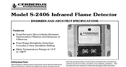
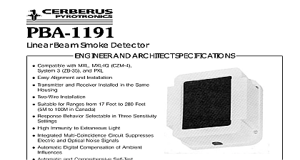
Cerberus Pyrotronics S121 S122 Solar Blind Infra-Red Flame Detector 6144

File Preview
Click below to download for free
Click below to download for free
File Data
| Name | cerberus-pyrotronics-s121-s122-solar-blind-infra-red-flame-detector-6144-9705486123.pdf |
|---|---|
| Type | |
| Size | 1.08 MB |
| Downloads |
Text Preview
S121 and S122 Flame Detectors AND ARCHITECT SPECIFICATIONS Insensitive to Electric Arcs Intrinsically Safe Weatherproof Two Wire Supervised Built In Response Indicator Pyrotronics S121 and S122 are infrared flame designed to provide an early warning of flaming involving all types of hydrocarbons and material carbon S121 and S122 detectors make use of of the infrared sensors and filters to provide major improve in rejection of deceptive phenomena such as arcs heaters and artificial light sources while the inherent advantages of infrared type flame In the detectors design special attention has paid to the optimization of the optical bandwidth optical filters are used to restrict the response of S121 to a narrow band of the infrared spectrum which its response to sunlight to a level at which it is blind S121 and S122 responses are not seriously affected lens fouling caused by oil or dust as compared to U V flame detectors The use of micro power electronic allows the S121 and S122 to operate on a conven two wire detection circuit This two wire circuit allows to be connected to a fire alarm zone in the same as conventional Cerberus Pyrotronics smoke and detectors S121 and S122 each have specific application in general they are intended for the protection high risk areas in which the materials that are likely to will produce flames along with the production of dioxide materials of this type are Flammable Liquids and Gases Paper and Packaging Materials Foamed Plastics detectors are not designed to respond to flames from fuels which do not contain carbon e g and ammonia and should be used with such only after satisfactory testing S121 and S122 were tested and approved by FM and considered to be intrinsically safe when used in with either the Cerberus Pyrotronics System 3 the ZS 30 intrinsically safe module or the MXL CZM 1 ISI 1 shunt barrier With proper installation the S121 S122 can be used safely in Class 1 Division 1 A B C D hazardous locations Solar blind of the S121 make this detector ideally for outdoor areas where other infrared detectors produce unwanted alarms Some of these areas refineries gas production plants petrochemical facilities hangars and other airport facilities sites offshore drilling platforms etc S122 is suited best for indoor applications such as storage facilities and other large indoor where requirements for the detector to be solar blind minimal NUMBER detectors are essentially line of sight devices special care must be taken in applying them to that their ability to respond to fire in the area which to be protected will not be compromised by the pres of intervening structures or other opaque objects or The detectors should be installed at a point provides the most direct line of sight with the source of fire used with Cerberus Pyrotronics equipment in safe the S121 S122 are fully compatible with other 3 compatible detectors with up to thirty 30 S121 flame detectors per ZU 35 or a combination of where the total permitted load on the zone would exceed 3.0 mA maximum at 22 VDC used with Cerberus Pyrotronics equipment in Areas the S121 S122 must be used in con with the intrinsically safe module ZS 30 or CZM 1 a limit of five 5 S121 S122 per zone and Performance fires involving carbonaceous material produce quantities of carbon dioxide This part of the combus process gives rise to a very high level of infrared in the wavelength region between 4.2um and The S121 responds only to infrared radiation in the of 4.4um making the S121 resistant to sunlight to a where it is solar blind The S122 responds to a wider of infrared radiation produced by the combustion This range which is between 4.2um and 4.7um the detector more sensitive to the detection of However although it is resistant to sunlight re it is not totally solar blind The radiation from a fire in a characteristic way and the detector uses this Response of Gasoline Fire signal to give extra discrimination against interfering sources such as flickering fluorescent lamps and blown sunlit pools of water The detector circuit the signal within the flicker frequency region and the amplitude of the signal is above a preset threshold for three seconds an alarm is signaled If the signal is this threshold level the detector will not alarm level of the signal depends upon the size of the flame its distance from the detector Since different fuels different burning characteristics they will burn at rates therefore producing different flame sizes at same time Response difference in detection range for various fuels appears chart A Diagrams 1A and 1B more specifically describe typical response of a gasoline fire refer to diagrams 2A and 2B for information in to angle of incidence A RANGE of a FIRE with a PAN AREA OF 1 SQ FT I M S Oil Glycol ft ft ft ft ft ft ft ft ft ft ft ft S121 will detect a 1 sq ft fully developed gasoline fire 61 ft within 3 seconds A 4 sq ft fully developed fire would be detected at 122 ft Installation are specific for the environment and risk S122 has a greater sensitivity than the S121 and is indoors where interference from deceptive infrared is less likely The S122 will detect a 1 sq ft fully gasoline fire at 88 ft within 3 seconds A 4 sq fully developed gasoline fire would be detected at 177 Installation arrangements are specific for the environ and risk situation Shipping of View Voltage Current Current Indicator Temperature Humidity in x 3.15 in x 2.36 in lb for S121 110 for S122 charts below VDC polarity conscious max 20V max LED visible from front 20 to 158 70 at 4 20 to 70 approved at to 40 with detection reduced to 1 2 normal to 95 continuous 100 Mutual 3260 3610 or outdoors Mutual Approved CSA Standards Ap for Intrinsic Safety Register of Shipping of S121 122 Detector Sensitivity Relative Range Versus Angle of Incidence Relative Range Versus Angle of Incidence Graphs 2A 2B above explain the relative sensitivity change resulting from the angle of view For example on Graph 2A a head on view of the fire 0 has the detector performing at relative sensitivity while a fire at 40 view has sensitivity reduced to approximately 70 Wiring NON HAZARDOUS AREA detector has screw terminals and polarity must be An end of line device is required across the of the last detector to allow line monitoring installation instructions P N 315 085258 for HAZARDOUS AREA in a hazardous area will require the detector to be taken through the Shunt Diode Safety Barrier in a safe area and furnished with Cerberus Py Model ZS 30 Intrinsically Safe Module or CZM 1 must comply with the Installation Instructions for ZS P N 315 024056 or for CZM 1 P N 315 090725 installing the detector it is recommended that be given to the use of flexible cable conduit a nearby junction box to allow for detector direction In cases where optimum risk viewing orienta can be predetermined a flexible cable conduit would be necessary The use of other than Cerberus Pyrotronics detectors and bases with Cerberus control equipment will be considered a misapplication of Cerberus Pyrotronics and as such void all warranties either expressed or implied with regards to loss liabilities and or service problems Pyrotronics Ridgedale Avenue Knolls NJ 07927 201 267 1300 201 397 7008 in U S A Pyrotronics East Pearce Street Hill Ontario 1B7 CN 905 764 8384 905 731 9182 1996 sheet dated 6 94


