Siemens ACM-1 Audio Control Module, Installation Instructions

File Preview
Click below to download for free
Click below to download for free
File Data
| Name | siemens-acm-1-audio-control-module-installation-instructions-7982351460.pdf |
|---|---|
| Type | |
| Size | 836.60 KB |
| Downloads |
Text Preview
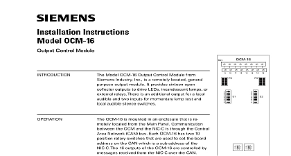
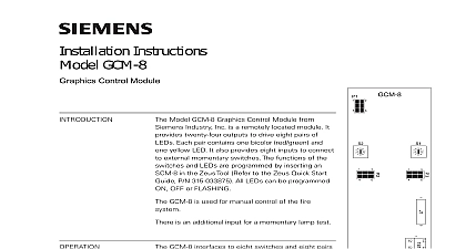
Installation Instructions ACM 1 Control Module Model ACM 1 Audio Control Module Siemens Industry Inc is the master module for the MXLV audio system module controls all Voice related func It has two yellow LEDs TROUBLE indicates ACM 1 troubles and the LED monitors network activity to Figure 1 for the location of the These troubles also appear on the panel has a supervised tone generator provides a variety of tones for use the system Each system can have two the available tones The tones are set CSG M If an application requires tone use the P6 connector on the for the BTC 1 Backup Tone card to Figure 1 ACM 1 occupies one network address switch S102 shown in Figure 2 is used set the network address that was chosen CSG M for the ACM 1 module The ACM 1 controls and supervises the circuit for the microphone wiring for the retractable cord The circuit controls the volume any signal that enters the circuit When the microphone key is pressed ACM 1 sends the preannounce tone was configured in CSG M making microphone the source for audio 1 1 PC Board Industry Inc Technologies Division Park NJ 315 092083 10 Building Technologies Ltd Safety Security Products Kenview Boulevard Ontario 5E4 Canada The ACM 1 also controls a small local in the MMM 1 module Any several signals available in the can be sent to this speaker if in CSG M Three supervised riser circuits provide power audio signals to the OCC 1 to sent to power amplifiers The ACM 1 also connect these risers to an non emergency signal source use in non emergency audio The Audio Control module communi with the VSM 1 Voice Switch the VLM 1 Voice LED and the VFM 1 Fan Control that are part of the system VSM 1 modules provide firefighters a means of controlling nonautomatic of the MXLV system VLM 1 modules provide status of the System The VFM 1 provide the system operator automatic and manual control and of fan control functions for management These functions set in CSG M For more information the VSM 1 VLM 1 and VFM 1 to the MXLV Manual P N 315 and the VLM 1 VSM 1 VFM 1 P N 315 092064 The ACM 1 controls the warden page comes from the TMM 1 Telephone module When activated the page becomes the audio for selected speaker zones all system power before instal first battery and then AC To up connect the AC first then the set the network address of the Remove the ACM 1 from its protective Refer to the CSG M configuration for the address of the ACM 1 Set the ACM 1 address on switch S102 to Figure 2 for the location of 2 the ACM 1 S102 Find the correct setting for the ACM 1 When an MHD 3 is used in the top of the enclosure instead of MKB 2 Mount the ACM MPT bracket on the studs located in the lower right corner of the MME 3 backbox are the same studs used for TSP 40 printer Secure the with the four nuts provided Figure 3 Be sure that P1 is in the upper right corner of the ACM Refer to 3 Mount the ACM 1 PC over the six threaded mount spacers Fasten the module in place with the No 6 screws provided one of spacers is used for support to Figure 3 in Table 1 on page 6 of and use dipswitch S102 SW1 through SW8 to set the for the module To open a dipswitch press on the side of the marked OPEN To a dipswitch press down the side of the dipswitch the side marked open a slide switch push slide to the side opposite side marked ON To close a switch push the slide to side marked ON mount the ACM 1 module ACM 1 may be mounted in two differ locations in the enclosure depending on or not there is an MKB 2 in the In some cases an MHD 3 is instead of the MKB to enable the use more VSMs in a system When an MKB 2 is in the top of the system enclosure Mount the ACM 1 module on the of the MKB 2 front panel the ANN 1 module Check the ribbon cable connector P1 is the upper left corner of the board mounting With the board in that position place module over the five threaded spacers See Figure 2 Fasten the module in place with the 6 screws provided 3 Mounting of ACM 1 wire the ACM 1 ACM 1 can be wired in two different One wiring configuration is if an MMB or PSR supplies the and data communications See 4 other wiring configuration is used a PS 5N7 supplies the power and communications as in a remote board See Figure 5 wiring information below is unaffected whether the ACM 1 module is in the or lower position of the enclosure that all cables that con to the ACM 1 are polarized connect in one way only DO FORCE THEM The location pin 1 on a connector is indicated marks on the pin or by color on the wires In Nos 1 and below be sure the black tracer is close to the 1 To wire the ACM 1 in an enclosure has an MMB or a PSR Refer to 4 Connect the long 15 ribbon cable 555 192238 from the MMB P8 PSR 1 P5 to P5 on the ACM 1 Connect the short 15 conductor cable P N 555 192242 from P3 to P4 on the ACM 1 Connect the 14 conductor ribbon P N 555 192236 from P3 to P1 on the ACM 1 if Connect the 50 conductor ribbon P N 555 192201 from P3 to P2 on the ACM 1 Connect the 5 conductor wire cable 600 190220 from TBM 2 P2 P3 on the ACM 1 P6 on the ACM 1 is connected to an BTC 1 module if used an MMM 1 is used connect the 9 cable attached to the to P7 on the ACM 1 to MMB 2 3 P8 to PSR 1 P5 to PIM 1 P1 Cable 555 192238 an ACM 1 that is Mounted on an MKB 2 4 To wire an ACM 1 module when is used to supply power and data communication instead of MMB or a PSR Connect the long 15 conductor cable P N 555 192238 from PS 5N7 P1 to P5 on the ACM 1 Connect the 50 conductor ribbon P N 555 192201 from P3 to P2 on the ACM 1 Connect the 5 conductor wire cable 600 190220 from TBM 2 P2 P3 on the ACM 1 an ACM 1 in a Remote Expander Enclosure 5 RATINGS additional information on the MXL MXLV System to the MXL MXLV Manual P N 315 092036 7 6 5 4 3 2 1 7 6 5 4 3 2 1 7 6 5 4 3 2 1 7 6 5 4 3 2 1 ADDRESS PROGRAMMING 1 ILL EGAL ILL EGAL ILL EGAL OOO X X O XOO OO XO X OO X XO OOO X X X XO OO O XOO X O XO XO OO XO X X O X XO O OO X XO X OO X X XO OOO X X X X XOO OO XO OO X XO O XO O XOO X X XO XO O O XO XO X O XO X XO OO XO X X X XXOO O O X XO O X O X XO XO OO X XO X X O X XXOO OO X X XO X OO X X XXO X X X XX XOOO OO XOO OO X XOO O XO XO OO X X XOO XO O XO O XO X XO O X XO O XOO X X X XO XOO O XO XO O X XO XO XO O XO XO X X XO XXOO O XO X XO X O XO X XXO XO X X XX X XOOO O XXOO O X XXOO XO O X XO O X X XXO XOO O X XO XO X O X XO XXO X XO X XX XX XOOO O X XXOO X O X XXO XO X X XO XX O X XX XOO X X XXO X X X XX XO X X X XX X