Siemens AD2-P AD2-PR AD2-XHR Air Duct Monitoring Housings Installation Instructions

File Preview
Click below to download for free
Click below to download for free
File Data
| Name | siemens-ad2-p-ad2-pr-ad2-xhr-air-duct-monitoring-housings-installation-instructions-7413569082.pdf |
|---|---|
| Type | |
| Size | 760.52 KB |
| Downloads |
Text Preview
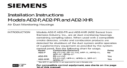
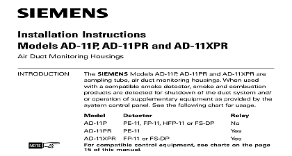
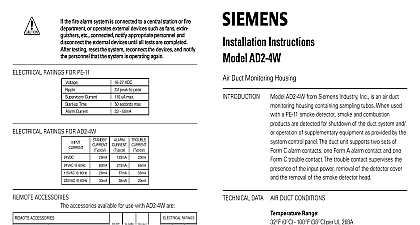
Installation Instructions AD2 P AD2 PR and AD2 XHR Duct Monitoring Housings DATA DUCT CONDITIONS AD2 P AD2 PR and AD2 XHR AD2 Series from Building Technologies Inc are air duct monitoring containing sampling tubes When used with a smoke detector smoke and combustion prod are detected for shutdown of the duct system and or of supplementary equipment as provided by the control panel See the following chart for usage compatible control equipment see charts on the page of this manual Range 0OC 100OF 38OC per UL 268 268A Range AD2 PR and AD2 XHR No altitude limitations Humidity Range non condensing non freezing Duct Velocity Range ft min AD2 P AD2 PR and AD2 XHR Tube Pressure Range of Differences than 0.01 and less than 1.2 inches of water column air duct detectors are designed for detection and of products of combustion in a duct system They not to be used for open area protection NOT USE air duct detectors with Alarm Verification Building Technologies Inc Fernwood Road Park New Jersey 07932 315 049708 2 315 049708 2 Building Technologies Safety Indicator AD2 Series duct smoke detectors provide early detec of smoke and products of combustion present in air through an HVAC duct supply return or both These are designed to prevent the recirculation of smoke in by the air handling system fans and blowers Com systems may be shut down in the event of smoke the correct installation of a duct smoke unit please refer NFPA 72 National Fire Alarm Code NFPA 90A Standard Installation of Air Conditioning and Ventilation Systems NFPA 92A Recommended Practice for Smoke Control the Models AD2 P AD2 PR and AD2 XHR are operat a sample of air is drawn from the duct and passed the sampling chamber by means of the input tube The air sample passes through the smoke mounted in the duct housing and is exhausted back the duct through the outlet tube detector is equipped with cover removal switch SW1 instantly provides a trouble condition upon removal of clear cover For all testing and inspection with the cover the cover removal switch designated as SW1 on must be manually depressed to simulate normal AD2 P AD2 PR and AD2 XHR contain an LED indicator on the smoke detector capable of flashing either one three distinct colors green yellow or red During each flash the microprocessor based detector checks the smoke in its sensing chamber its critical smoke sensing electronics are operating Building Technologies Safety 315 049708 2 315 049708 2 Building Technologies Safety CONTROL EQUIPMENT detector model number is the compatibility identifier equipment does not support remote accessories e g lamps or relays RATINGS FOR PE 11 RATINGS FOR FP 11 HFP 11 AND HFPO 11 ratings are not provided here for these detectors for detector loop loading along with loop wire specifications are provided in the applicable control instructions given in the above Compatible Control tables on the results of these checks the LED indicator as follows DUCT A CLOSED SYSTEM NO EXHAUST AIR INTAKE DUCT DUCT B PROVISION FOR EXHAUSTING PERCENTAGE OF RETURN AIR AIR INTAKE AIR DUCT DUCT C RETURN AIR UNDER POSITIVE PRESSURE SEPARATE BLOWER AIR INTAKE AIR AIR DUCT DUCT 2 Locations in Duct Systems 1 Mounting of Duct Housing Building Technologies Safety 315 049708 2 315 049708 2 Building Technologies Safety performance of the air duct detector unit may be affected by dirt or foreign matter on the sampling or detector If the air holes in the input sampling tube restricted the unit cannot receive a proper air and performance is impaired It is recommended the sampling tubes be checked and cleaned periodically detector maintenance program should consist of cleaning of dust from the detector head by using a cleaner For cleaning Models PE 11 FP 11 HFP 11 or refer to the detector Installation Instructions See A cleaning and test program is recommended for 6 month or more frequently if needed depending on the detector environment Consult your local code and requirements for required maintenance schedules no circumstances is the detector portion of the unit be disassembled by anyone other than an authorized Building Technologies Inc Systems Technician For contact your nearest authorized Siemens Building Inc Service Representative the fire alarm system is connected to a central station or fire or operates external devices such as fans extin etc connected notify appropriate personnel and the external devices until all tests are completed testing reset the system reconnect the devices and notify personnel that the system is operating again THE AIR DUCT HOUSING on Duct System guideline contains general information on duct smoke installation but does not preclude the NFPA listed Siemens Building Technologies Inc no responsibility for improperly installed duct To determine the correct installation position for AD2 Series duct smoke detector the following factors be considered A uniform non turbulent laminar airflow between 100 ft to 4,000 ft min must be present in the HVAC duct determine duct velocities examine the engineering that define the expected velocities or use Alnor model 6000AP velocity meter or equivalent To minimize the impact of air turbulence and stratifica on performance a duct smoke detector should be as far as possible downstream from any obstruc i e deflector plates elbows dampers etc In all confirmation of velocity and pressure differen within specifications is required pressure differential between the input sampling pressure tube and outlet low pressure tube for AD2 Series smoke duct detector should be greater 0.01 inches of water and less than 1.2 inches of a code compliant location supply or return side both for the installation of the duct unit that will easy access for viewing and serviceability When installing on the return side install duct units prior the air being exhausted from the building or diluted outside air When installing duct smoke units downstream of filters occurring in the filters will be detected but if the become blocked insufficient air flow throug