Siemens ALD-2I AnaIog Loop Driver, Installation Instructions

File Preview
Click below to download for free
Click below to download for free
File Data
| Name | siemens-ald-2i-anaiog-loop-driver-installation-instructions-2057943186.pdf |
|---|---|
| Type | |
| Size | 695.55 KB |
| Downloads |
Text Preview
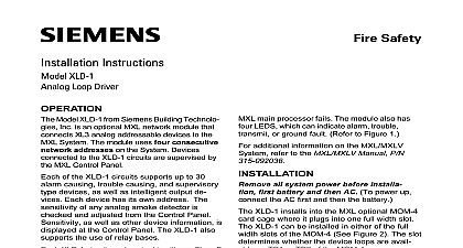
Installation Instructions ALD 2I Loop Driver Model ALD 2I from Siemens Industry Inc an optional MXL MXLV MXL IQ network that connects intelligent addressable to the MXL MXLV MXL IQ System module uses two consecutive network on the System Devices connected the ALD 2I circuits are supervised by the Control Panel of the ALD 2I circuits supports up to 60 causing trouble causing security and type devices as well as remote and intelligent output devices Each has its own address The sensitivity of intelligent smoke detector is checked and from the Control Panel Sensitivity as as other device information is displayed at Control Panel The ALD 2I also supports the of relay bases ALD 2I circuit can be wired in either a Class or Class A configuration When using Class B is permitted with no loss of supervision ALD 2I module has an on board micro which provides it with the ability to and to initiate alarm conditions even if MXL main processor fails The module also four LEDs which can indicate alarm trouble or ground fault Refer to Figure 1 1 Board Industry Inc Technologies Division Park NJ 315 091464 13 Building Technologies Ltd Safety Security Products Kenview Boulevard Ontario 5E4 Canada all MXL IQ installations cut jumper G2 all system power before installation battery then AC To power up connect the first then the battery ALD 2I installs into the MXL optional module cage Model MOM 4 It plugs into one full slot in the MOM 4 The ALD 2I can be in either the upper or lower slot of the See Figure 2 The position determines the device loops are available on TB1 or of the MOM 4 the MXL software revision level is 3.2 or higher jumper G2 If the level is below 3.2 do not it the ALD 2I is installed in the MOM 4 set network address using switch S1 See Figure Set it to the lower of the two corresponding selected for it in the CSG M The address must be odd Follow the appropri switch positions in Table 1 on the back to set address table below illustrates sample ALD 2I addresses the address is set install the ALD 2I in the being sure that the module is riding in card guides and is firmly seated in the card connector Eliminate all troubles from each before installing the next one connections for the two addressable zones are shown in Figure 3 Ratings Refer to Figure 3 Ratings circuits are rated 30 VDC unfiltered full wave peak max VDC unfiltered full wave peak max 60 devices in alarm Devices All circuits are power limited to NFPA 70 per 760 Each detector or group of detectors use a 2 wire circuit of at least 18 AWG fixture wire enclosed in conduit 18 AWG limited energy shielded cable conduit if permitted by local building 2 for ALD 2I No end of line device is required for these loops Up to 60 detectors can be used per loop See table at the right for a list of compatible Use any combination of those The compatibility identifiers for the compatible are the model numbers listed at the Total circuit resistance must not exceed 100 capacitance between loop and loop between loop and chassis between loop and chassis T tapping is not allowed on Class A loops additional information on the MXL MXLV refer to the MXL MXLV Manual P N 315 additional wiring information refer to Wiring for MXL MXL IQ and MXLV P N 315 091772 revision 6 or higher A WIRING T TAPPING ALLOWED B WIRING ALLOWED 1 2 LOOP MAY BE WIRED AS A OR CLASS B END OF LINE DEVICE REQUIRED CIRCUITS SUPERVISED AND LIMITED PER NEC 760 AND NEGATIVE GROUND DETECTED AT 40K OHMS TERMINALS 1 8 DEVICE USED 11 12 14 15 16 1 2 3 Wiring Diagram IN FULL CONFORMANCE WITH STYLE 6 IN FULL CONFORMANCE WITH STYLE 4