Siemens ALI-8B Enclosure Assembly replacement plate, Installation Instructions

File Preview
Click below to download for free
Click below to download for free
File Data
| Name | siemens-ali-8b-enclosure-assembly-replacement-plate-installation-instructions-7453128609.pdf |
|---|---|
| Type | |
| Size | 635.89 KB |
| Downloads |
Text Preview
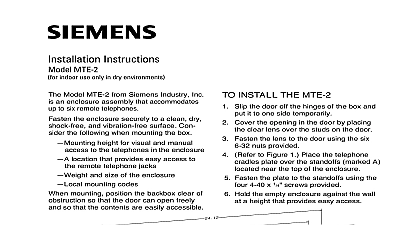
Installation Instructions ALI 8B indoor use only in dry environments Model ALI 8B from Siemens Industry is an enclosure assembly that accommo up to eight TRI S D R modules to the interface between the MXL and the control panels dry contact devices also TRI S D R Installation Instructions 315 049481 the enclosure securely to a clean dry and vibration free surface Con the following when mounting the box height for visual and manual to the modules in the enclosure and size of the enclosure mounting codes maximum cable length of 200 feet AWG for the TRI S D R modules to AnaLASER equipment dry contact mounting position the backbox clear of so that the door can open freely so that the modules are easily accessible INSTALL THE ALI 8B Slip the door off the hinges of the box and it to one side temporarily Cover the opening in the door by placing black metal plate over the studs on the door 1 for the ALI 8B Industry Inc Technologies Division Park NJ 315 098327 3 sure that the 3 position screw terminal the top row of TRIs is facing downward and 3 position screw terminal on the bottom of TRIs is facing upward Building Technologies Ltd Safety Security Products Kenview Boulevard Ontario 5E4 Canada Fasten the plate to the door using the six nuts provided to Figure 1 Remove knockouts in the where field wiring is required Place the interface plate over the four studs A in Figure 1 and secure it to the with the four 6 32 nuts provided Hold the empty enclosure against the wall at height that provides easy access Mark drill points on the wall in the center of two slots on the upper rear of the box Drill the two holes and screw in the top using 1 4 or 3 8 mounting hardware supplied Leave a small gap between wall and each top screw 9 Mount the enclosure on the two screws and install the bottom screws Tighten all screws securely against the back of the enclosure Place 2 8 32 screws in the interface plate in positions marked B for each TRI module install Refer to Figure 1 for the screw When mounting TRI modules one is placed in the top left hand corner of TRI and the other screw is placed in the right hand corner of the TRI Do not the screws at this time Insert the TRI modules on the screws of the plate in two rows by twisting them position as shown in Figure 1 Make that the 3 position screw terminal on top row of TRIs is facing downward the 3 position screw terminal on the row of TRIs is facing upward the TRIs into position by tightening screws Slip the door back on the hinges of the 315 098327 3