Siemens CC-5 CC-2 System Cardcage, Installation Instructions

File Preview
Click below to download for free
Click below to download for free
File Data
| Name | siemens-cc-5-cc-2-system-cardcage-installation-instructions-9475823106.pdf |
|---|---|
| Type | |
| Size | 1.32 MB |
| Downloads |
Text Preview
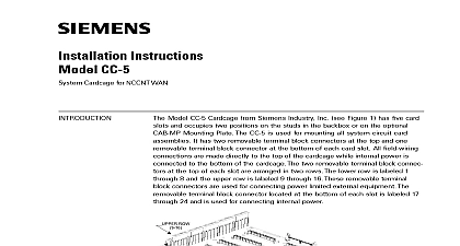
Installation Instructions CC 5 CC 2 Cardcage Model CC 5 Cardcage from Siemens Industry Inc see Figure 1 has five card and occupies two positions on the studs in the backbox or on the optional CAB Mounting Plate The Model CC 2 Cardcage see Figure 2 has two card slots and one position on the studs in the backbox or on the optional CAB MP Plate The CC 5 and CC 2 are used for mounting all system circuit card They each have two removable terminal block connectors at the top and removable terminal block connector at the bottom of each card slot All field connections are made directly to the top of the cardcage while internal power connected to the bottom of the cardcage The two removable terminal block at the top of each slot are arranged in two rows The lower row is labeled through 8 and the upper row is labeled 9 through 16 These removable terminal connectors are used for connecting power limited external equipment The terminal block connector located at the bottom of each slot is labeled 17 24 and is used for connecting internal power shown without card guides installed 1 Card Cage 2 Card Cage CC 5 and CC 2 provide a central point for mounting circuit card assemblies If a requires power it is applied through the removable terminal block at the bottom the cardcage All external devices for the card are connected to the card through two removable terminal blocks at the top of the cardcage The circuit card are connected to the HNET and CAN bus through the connectors on the 315 033035 6 Inc Inc Inc Industry Inc Inc TTTTTececececechnologies Di Di Di Division Di CC 5 and CC 2 are shipped with the card guides removed The card guides are to assist in installation They can be installed either before or after the cardcage installed in the enclosure For ease of installation the card guides have been to be installed after the field wiring has been completed Guide Installation 3 upper and lower card guides are keyed differently and are not interchangeable that the card guide keys fit easily into the holes in the motherboard to damage upper card guide has a label on each slot that can be used to identify module installed in the slot If desired complete the label before the upper card guide the upper card guide and secure with the captive screws the lower card guide and secure with the captive screws CARD GUIDE CARD GUIDE SCREWS PIN HOLE SCREW RETAINERS 3 Guide Installation CC 5 Shown all system power before installation first battery then AC To power up the AC first then the battery CC 5 and CC 2 mount at the back of the enclosure of the FireFinder XLS Desigo Safety Modular Cerberus PRO Modular system on the studs in the backbox or on optional Mounting Plate CAB MP The Mounting Plate may be located either Industry Inc Technologies Division 315 033035 6 or of the enclosure to perform this installation procedure If the Mount Plate is located the enclosure you will have to gain access to it by opening enclosure Inner and Outer doors If the Mounting Plate is located outside of the place it in front of you so that the word is at the top and away from row of studs in the backbox or each Mounting Plate can hold a maximum of CC 5 cardcages There are three possible locations for mounting the CC 5 left in the backbox or on the Mounting Plate in positions 1 2 the center of the row in the backbox or on Mounting Plate in positions 2 3 right in the backbox or on the Mounting Plate in positions 3 4 CC 2 is most effectively used to add two more card slots in a row that already one CC 5 and another 1 position module i e PSC 12 It is best installed in a adjacent to the CC 5 only one CC 5 cardcage is to be installed it is normally installed on the left of a row in the backbox or on the Mounting Plate is a top and bottom to the Mounting Plate The top is where the word is on the Mounting Plate When the cardcage is mounted correctly on the Plate it will be flush on the top bottom and left with the Mounting Plate the two screw holes in the center of the cardcage motherboard will be over posts four 10 32 screws in the threaded posts at the top left of Position 1 right of Position 2 bottom left of Position 1 and the bottom right of 2 on the Mounting Plate Screw each of the 10 32 screws into the posts 5 6 turns Refer to Figure 3 the cardcage over the four screws on the Mounting Plate and slide it or towards you to rest on the four screws Refer to Figure 4 When cardcage is in the correct position it will be flush with the top bottom left side of the Mounting Plate the two 10 32 screws in the center of the cardcage motherboard the left and right edge the six screws Industry Inc Technologies Division 315 033035 6 1 2 3 4 TOP THREADED POSTS TOP THREADED POSTS BOTTOM THREADED POSTS BOTTOM THREADED POSTS 1 2 3 4 4 Of The CC 5 and CC 2 On The Optional CAB MP DOWN CARDCAGE UNTIL ON TOP LEFT AND BOTTOM TWO 10 32 SCREWS WHEN WITH THREADED STUDS 5 The CC 5 and CC 2 On The Optional CAB MP Industry Inc Technologies Division 315 033035 6 the top and bottom of the CC 5 and CC 2 and adjacent to each card slot are terminal blocks The wiring to the two terminal block connectors at the top the CC 5 and CC 2 is power limited The wiring to the terminal block connector at bottom of the CC 5 and CC 2 is non power limited Connect External Wiring The Card Slots 6 the wire to be connected in the desired opening in the side of the terminal block the appropriate locking screw Connect The Bus 6 Terminal Block On The CC 5 and CC 2 Data bus connectors on the cardcage motherboard are P1 and P2 Refer to 7 They are 60 pin keyed male connectors with connector extractors Open the connector ejectors out of the vertical position and away from the body the female cable connector into the male connector P1 or P2 on the motherboard Gently press the cable connector into the connector As the cable connector is pressed in the connector will begin to move to the vertical position When the cable connec is fully seated the connector ejectors will be vertical the 60 pin bus cable long P N 500 633997 when the PSC 12 PSX 12 is located a different row in the backbox or on a different CAB MP Industry Inc Technologies Division 315 033035 6 Connect The CAN Bus CAN bus P3 is a six pin connector located just above P1 on the cardcage Refer to Figure 7 It is used to supply CAN communications and to the LED Control Modules LCM Switch Control Modules SCM Control FCM Master Voice Microphone LVM and Master Firefighters Telephone The connector is keyed and requires no special instructions for cable connec Use cable CCL P N 500 634214 to connect from CAN bus P3 on CC 5 and CC to the desired module CAN power must be supplied to E11 CC 5 or E5 CC 2 to Figure 8 for wiring details EJECTORS VERTICAL POSITION 7 Of Connectors CC 5 Shown 8 Power For CAN Bus Industry Inc Technologies Division 315 033035 6 Specifications x 14.25 Ratings x 14.25 PSC 12 supplies the power to the two 60 pin Data connectors P1 and P2 in the CC 5 and CC 2 The rating on P1 and P2 for all CC 5s in any given is as follows VDC VDC Amps max Amps max PSC 12 Installation Instructions P N 315 033060 and the PSX 12 Installation P N 315 034050 for complete power supply loading calculations Industry Inc Technologies Division 315 033035 6 security disclaimer products and solutions provide security functions to ensure the secure operation of comfort fire safety security management and phys