Siemens CMI-300 Interface Module, Installation Instructions
File Preview
Click below to download for free
Click below to download for free
File Data
| Name | siemens-cmi-300-interface-module-installation-instructions-9516320748.pdf |
|---|---|
| Type | |
| Size | 746.57 KB |
| Downloads |
Text Preview
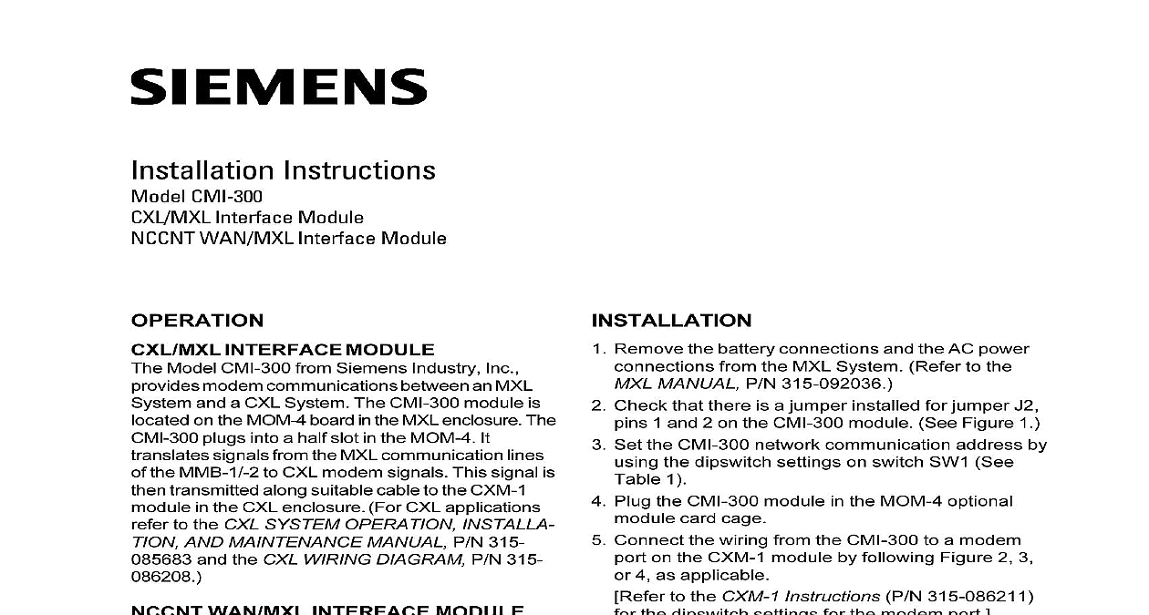
Installation Instructions CMI 300 Interface Module WAN MXL Interface Module INTERFACE MODULE Model CMI 300 from Siemens Industry Inc modem communications between an MXL and a CXL System The CMI 300 module is on the MOM 4 board in the MXL enclosure The plugs into a half slot in the MOM 4 It signals from the MXL communication lines the MMB 1 2 to CXL modem signals This signal is transmitted along suitable cable to the CXM 1 in the CXL enclosure For CXL applications to the CXL SYSTEM OPERATION INSTALLA AND MAINTENANCE MANUAL P N 315 and the CXL WIRING DIAGRAM P N 315 WAN MXL INTERFACE MODULE Model CMI 300 provides modem communications an MXL System and an NCCNT WAN The CMI 300 module is located on the MOM 4 in the MXL enclosure The CMI 300 plugs into a slot in the MOM 4 It translates signals from the communication lines of the MMB 1 2 to CXL signals This signal is then transmitted along cable to the HUB 4 module in the COM 1 For NCCNT WAN applications refer to the GRAPHICS Manual P N 315 049679 RATING line attenuation 2.5KHz per modem channel pair Industry Inc Technologies Division Park NJ 315 091259 10 Remove the battery connections and the AC power from the MXL System Refer to the MANUAL P N 315 092036 Check that there is a jumper installed for jumper J2 1 and 2 on the CMI 300 module See Figure 1 Set the CMI 300 network communication address by the dipswitch settings on switch SW1 See 1 Plug the CMI 300 module in the MOM 4 optional card cage Connect the wiring from the CMI 300 to a modem on the CXM 1 module by following Figure 2 3 4 as applicable to the CXM 1 Instructions P N 315 086211 the dipswitch settings for the modem port the wiring from the CMI 300 to a modem on the HUB 4 module by following Figures 5 or as applicable to the HUB 4 Instructions P N 315 099302 Re apply AC power to the MXL System then the batteries to the system TEST AND an initiating device is activated and the MXL but the CXL or NCCNT WAN panel fails to follow the steps below Check the dipswitch address settings on the CMI 300 Check the XMIT LED DS2 on the CMI 300 module activity approximately every 20 seconds the LED Building Technologies Ltd Safety Security Products Kenview Boulevard Ontario 5E4 Canada MXL network communication Check for proper field wiring connections between CMI 300 and the CXM 1 or HUB 4 module check that the CXL or NCCNT WAN System powered Move the CMI 300 wiring to another port on the or HUB 4 and check for communications If the problem persists replace the CMI 300 reset the dipswitch address settings and the unit none of the steps above solves the problem refer the MXL MANUAL P N 315 092036 PROGRAMMING to the CSG M MANUAL P N 315 090381 for instructions on configuring the MXL Control 1 CLASS B STYLE 4 AWG MIN USE 2 WIRE COPPER CABLE 105 C 300V 18 AWG OR STRANDED MAX 7 STRANDS All wiring must conform to local codes and to the authority having jurisdiction over the installation All circuits are rated 2 volts peak to peak 1.3mA All circuits are supervised Operates in full conformance with Style 4 Type 3 Communication circuit Class B Style 4 Wiring Connection 2 STYLE 7 2 WIRE CABLE C 300V 18 AWG OR STRANDED 7 STRANDS 2 WIRE 18 AWG CABLE MIN OHM MAX LINE RESISTANCE PER PAIR All wiring must conform to local codes and to the authority having jurisdiction over the installation All circuits are rated 2 volts peak to peak 1.3mA All circuits are supervised Operates in full conformance with Style 7 3 Style 7 Connection NON SWITCHED TELEPHONE LINE OHMS IMPEDANCE CLASS B STYLE 4 OHMS 5 140 820366 All wiring must conform to local codes and to the authority having jurisdiction over the installation All circuits are rated 2 volts peak to peak 1.3mA All circuits are supervised Operates in full conformance with Style 4 Type 3 Communication circuit Class B Style 4 Connection Using Conditioned Non Switched Telephone Line 4 CLASS B STYLE 4 AWG MIN 2 USE 2 WIRE COPPER CABLE 105 C 300V 18 AWG OR STRANDED MAX 7 STRANDS All wiring must conform to local codes and to the authority jurisdiction over the installation All circuits supervised 3 4 SLOT OF CC 5 WITH HUB 4 INSTALLED Class B Style 4 Wiring Connection With HUB 4 5 All wiring must conform to codes and to the having jurisdiction the installation All circuits supervised Style 7 Wiring Connection With HUB 4 6