Siemens CRC-6 Controllable Relay Module, Installation Instructions

File Preview
Click below to download for free
Click below to download for free
File Data
| Name | siemens-crc-6-controllable-relay-module-installation-instructions-8095736124.pdf |
|---|---|
| Type | |
| Size | 669.29 KB |
| Downloads |
Text Preview
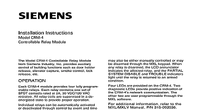
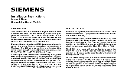
Installation Instructions CRC 6 Relay Module Model CRC 6 Relay Module from Siemens Industry Inc auxiliary control of building functions such as door release elevator capture lock release etc FAIL FAIL FAIL 1 ACTIVE 2 ACTIVE 3 ACTIVE 4 ACTIVE 5 ACTIVE 6 ACTIVE 1 Controllable Relay CRC 6 module provides six fully programmable relays relay contains one set of SPDT contacts rated at 4A VDC 120 VAC resistive and 3.5A 120 VAC 0.6 PF induc All relay coils are supervised to ensure proper operation relays can be automatically activated or deacti through control by event and time based logic con in the FireFinder XLS Desigo Fire Safety Modular PRO Modular system Each relay may also be manually controlled or may be disarmed through the XLS FCM2041 U2 Desigo Fire Safety FCM2041 U3 Cerberus PRO Modular When any is disarmed the LED on the CRC 6 indicates the relay and the PARTIAL SYSTEM DISABLE and indicators on the PMI PMI 2 PMI 3 XLS Desigo Fire Safety Modular FCM2041 U3 PRO Modular light until the relay is returned to an condition front panel of the CRC 6 contains one reset switch ten and three HNET address switches as shown in 1 reset switch is located on the top of the front panel the reset switch re initializes the CRC 6 operation LEDs follow the reset switch and their functions are as follows ON When indicates power for the is applied to card and Indicators FAIL OFF When illuminated indicates that card microprocessor has failed Inc Inc Inc Industry Inc Inc TTTTTececececechnologies Di Di Di Division Di 315 033250 12 FAIL FAIL 1 ACTIVE 2 ACTIVE 3 ACTIVE 4 ACTIVE 5 ACTIVE 6 ACTIVE OFF When illuminated indi that the HNET communication with CRC 6 has terminated and the card into degrade mode applicable only card resides in the HNET network OFF When illuminated indi that the 24V supply has dropped 18V OFF When illuminated indi that Relay 1 is active In the event a relay coil failure the LED will blink OFF When illuminated indi that Relay 2 is active In the event a relay coil failure the LED will blink OFF When illuminated indi that Relay 3 is active In the event a relay coil failure the LED will blink OFF When illuminated indi that Relay 4 is active In the event a relay coil failure the LED will blink OFF When illuminated indi that Relay 5 is active In the event a relay coil failure the LED will blink OFF When illuminated indi that Relay 6 is active In the event a relay coil failure the LED will blink rotary dial switches at the bottom of the front panel are used to set the HNET address of the CRC 6 the three digit HNET network address for the CRC 6 using the three rotary dial switches located near the bottom of the front panel Refer to Figure 1 for location of the switches The address for the CRC 6 must be the same as the selected for it in the Zeus Programming Tool To set the address turn the on each of the three dials to the numbers for the selected address For if the address is 123 set the pointer for the HUNDREDS dial to set the for the TENS dial to and set the pointer for the ONES dial to The range allowable addresses is from 001 to 251 leading zeros must be used Industry Inc Technologies Division 315 033250 12 all system power before first battery then AC To up connect the AC first then the field wiring to the CRC 6 is con to the terminal blocks of the CC card cage slot in which it is installed to Figure 2 top terminals 1 through 8 and 9 16 are connected to relays 1 4 bottom terminals 17 through 24 are to relays 5 6 The screw terminals can accommodate 12 18 AWG or two 16 18 AWG SHOWN IN INACTIVE STATE 1 2 NOT USE NOT USE 3 4 SLOT OF CC 5 NOT USE 5 6 2 Wiring Diagram CRC 6 plugs perpendicularly into one slot in the CC 5 card cage via two DIN connectors and can occupy any slot in the card cage the CRC 6 card into the card guides rightside up lettering on the front panel is the card in until the card edge connectors contact receptacles on the motherboard that the DIN connectors of the card and the card aligned properly The card can only plug in one to the card cage if it does not align DO NOT the card thumbs on the front panel adjacent to the captive and gently apply even pressure on the card the connectors seat in the receptacles on the with the captive screws the CRC 6 into a slot that was previously for a ZIC 4A may result in a short circuit on the 24V of the PSC 12 or PSX 12 Ensure that all ZIC 4A is removed prior to installation of the CRC 6 3 The CRC 6 Industry Inc Technologies Division 315 033250 12 Connect External Wiring the screw of the terminal by turning it counterclockwise the wire into the side of the terminal block the screw of the terminal block by turning it clockwise RATINGS Back Plane Current 20.5mA per Active Relay Terminal 24V Current Back Plane Current Standby Current 20.5mA per Active Relay 30VDC 120VAC resistive 120VAC 0.6PF security disclaimer products and solutions provide security functions to ensure the secure operation of comfort fire safety security management and physical security systems The security on these products and solutions are important components of a comprehensive security is however necessary to implement and maintain a comprehensive state of the art security that is customized to individual security needs Such a security concept may result in site specific preventive action to ensure that the building comfort fire safety security or physical security system for your site are operated in a secure manner These may include but are not limited to separating networks physically protecting system user awareness programs defense in depth etc additional information on building technology security and our offerings contact your Siemens or project department We strongly recommend customers to follow our security advisories provide information on the latest security threats patches and other mitigation measures http www siemens com cert en cert security advisories htm Industry Inc Technologies Division Park NJ Canada Ltd North Service Road East Ontario 0H6 Canada ID A6V10239114 315 033250 12