Siemens CXL-MP Mounting Plate, Installation Instructions

File Preview
Click below to download for free
Click below to download for free
File Data
| Name | siemens-cxl-mp-mounting-plate-installation-instructions-0486253791.pdf |
|---|---|
| Type | |
| Size | 688.54 KB |
| Downloads |
Text Preview
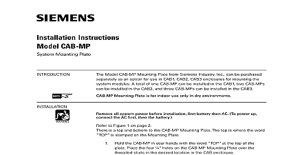
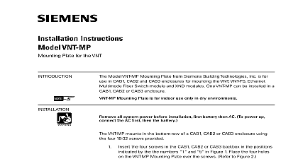
Installation Instructions CXL MP Plate the Model CXL MP mounting plate from Siemens Industry Inc to upgrade CXL Systems installed in Model EBX 1 backboxes to NCCNT WAN Systems CXL MP accommodates COM 1 WAN System components Additional COM 1 component setup can be referenced in the FireFinder Network Command Graphics Manual P N 315 049679 this conversion the maximum battery size that can be used in the backbox is AH If a larger battery is required use either a BB 55 or CAB BATT battery box convert an EBX 1 backbox from a CXL System to a COM 1 component system must first disassemble the CXL and then assemble the COM 1 This two part is described in detail below OF CXL SYSTEM to Figure 1 on page 2 all system power first battery and then AC the input and output power wires from the line filter COM 1 WAN System uses batteries as a back up power source If a UPS was for the CXL System disconnect it Disconnect the AC power wires from the CXA 1 Disconnect all connections from the CXA 1 to the CXB 1 Remove and save hardware that secures the CXA 1 to the enclosure Remove the CXA 1 Disconnect the wiring to all modules in the CXB 1 and identify the wires and save the hardware that secures the CXB 1 to the enclosure the CXB 1 the batteries from the enclosure if used and save the hardware that secures the battery tray to the enclo Remove the battery tray if used 315 048596 7 Inc Inc Inc Industry Inc Inc TTTTTececececechnologies Di Di Di Division Di 1 Of CXL System compliance with NEC Article 760 all power limited fire protective signaling must be separated a minimum of inch from all of the following wiring within a control panel light 1 or non power limited fire protective signaling conductors meet these requirements the following guidelines must be observed when modules and wiring to this control panel installing power limited field wiring the installer must comply with NEC article which states fire alarm power limited circuits are installed using Types FPL FPLR FPLP or substitute cable provided these power limited cable conductors extending the jacket are separated by a minimum of 0.25 in 6.35 mm or by a noncon sleeve or nonconductive barrier from all other conductors to Figure 2 for an example of Power Limited Wiring using a CXL MP Industry Inc Technologies Division 315 048596 7 FAIL FAIL NET FAIL FAULT 12 FAIL 4A FAIL AC N GND Limited Wiring Limited Wiring 36 connection P N 600 134852 with CXL MP 2 the CXL MP OF COM 1 WAN SYSTEM the CXL MP over the studs that previously secured the CXA 1 and the to the enclosure making certain the word is placed at the top the enclosure Refer to Figure 3 Using the hardware that was saved removing the CXA 1 and CXB 1 secure the CXL MP plate to the Industry Inc Technologies Division 315 048596 7 Mounting Plate for existing in EBX 1 3 Of Mounting Holes For CXL MP Mounting Plate the required CC 5 card cage s PSC 12 power supply and PTB power board after careful consideration of NEC Article 760 for separa of power limited and non powered limited wiring Use the hardware with those modules to mount them to the CXL MP mounting Refer to the CC 5 Installation Instructions P N 315 099319 the PSC Installation Instructions P N 315 099321 and the PTB Installation Instruc P N 315 034877 Refer to Figure 4 for the location of the threaded on the CXL MP Mounting Plate CXL MP plate can accommodate a maximum of two CC 5 card cages a power supply and a PTB power termination board Two CC 5 card will provide the capacity to replace a maximum size CXL of 28 MXL XL3 Systems and expand that number to 36 MXL XL3 connecting the PSC 12 to the PTB use the 36 cable P N 600 supplied with the CXL MP Industry Inc Technologies Division 315 048596 7 1 2 THREADED POSTS THREADED POSTS 1 2 3 4 5 THREADED THREADED POSTS 4 Of Threaded Posts On CXL MP THREADED THREADED POSTS 3 4 5 the required number of HUB 4 modules in the CC 5 See the HUB 4 Instructions P N 315 099458 for programming and wiring the CXM 1 module of the CXL System provided four modem connections MXL XL3 Systems some of which might not be used The HUB 4 can up to 4 modem channels depending on its configuration Each MAIN 2 assembly can support up to two HUB 4 COM 2 boards HUB 4 COM 2 board can support two Modem Block boards thus up to four modem channels to Step 4 in DISASSEMBLY OF THE CXL SYSTEM to identify the that was disconnected from the CXM 1modules installed in the Connect that communication wiring to the HUB 4 modules the NIC C card into the CC 5 Follow the NIC C Installation Instruc P N 315 099320 for programming and wiring the NIC C to the Battery Size Calculation Form in the PSC 12 Installation Instruc P N 315 099321 to determine the correct battery size for your system the batteries into the backbox space permitting If batteries used are than 31AH install them in either a BB 55 or CAB BATT battery box Industry Inc Technologies Division 315 048596 7 a blank cover on the opening in the enclosure door using the DCX 1 package P N 500 684559 Place the cover in the opening in the making sure the studs are on the inside of the door Attach cover to using the DCX 1 hardware kit P N 545 084593 Refer to Figure 5 5 View of DCX 1 Installation power up the system connect the AC first and then the batteries the COM 1 System configuration label P N 575 248461 over the CXL label Industry Inc Technologies Division 315 048596 7 page has been left intentionally blank Industry Inc Technologies Division 315 048596 7 page has been left intentionally blank Industry Inc Technologies Division Park NJ2 Building Technologies Ltd Safety Security Products Kenview Boulevard Ontario L6T 5E4 Canada 315 048596 7