Siemens DB-3S X3RS Base, Installation Instructions

File Preview
Click below to download for free
Click below to download for free
File Data
| Name | siemens-db-3s-x3rs-base-installation-instructions-3472096851.pdf |
|---|---|
| Type | |
| Size | 653.86 KB |
| Downloads |
Text Preview
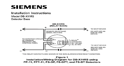
Installation Instructions Models DB 3S X3RS installation guideline is written in accordance with the installation of NFPA 72 National Fire Alarm Code and CAN ULC S524 Installation Of Fire Alarm Systems DIAGRAM FOR SIEMENS MODEL DB 3S USING DETECTORS Do not use looped wire under terminal 5 Break wire run to provide supervision of connection of line wires from Siemens Industry Inc device circuit See detector instructions for compatible and modules supported by detector zone connect to RL 30 RLI 1 or RLI 2 remote or remote relay RR 3 DIAGRAM FOR SIEMENS MODELS DB 3S AND DB X3RS IL SERIES DETECTORS OR FP SERIES DETECTORS Base DB 3S wires from Industry initiating circuit See for and RLI 2 1a Relay Model DB X3RS 120 VAC 30 VDC Next Base Not an of Next Base relay contacts are shown after a system reset pulse which represents the non alarm condition contact state may vary prior to system initialization 1 Diagram Industry Inc Technologies Division Park NJ 315 083225 15 Building Technologies Ltd Safety Security Products Kenview Boulevard Ontario 5E4 Canada PLACEMENT no specific spacings are allocated to these detectors maximum 30 center spacing 900 sq ft from NFPA Standard 72 Chapter 5 and may be used if practical as a guide or starting point in a installation layout This spacing however is based on ideal condi smooth ceiling no air movement and no physical obstructions all installations except in special circumstances such as in computer underfloors locate the detector on the ceiling a minimum of 12 inches a sidewall or on a wall between 4 and 6 inches from the ceiling questions arise regarding detector placement follow the drawings or approved by Siemens Industry Inc or by its authorized distribu This is extremely important The detector placements shown on these were chosen after a careful evaluation of all facets of the area factors such as air currents temperature humidity pressure the nature of the fire load are carefully considered Special consideration given to room or area configuration and the type ceiling sloped or flat or beamed Siemens Industry Inc s extensive experience in the of the system assures the optimum detector placement and is re in these drawings The sound engineering judgment of qualified must be followed WIRING Industry Inc s detectors should be interconnected as shown in 1 and wired to the control panel following the wiring connection draw installed on the inside face of each control panel cover Duplicate wiring is also in the Installation Operation and Maintenance Manual with every control panel Note any limitations on the number of permitted on each circuit MOUNTING USING THE DB 3S detector is provided with a separate base which attaches to a standard 4 square 4 inch octagonal or single gang electrical box with the box size and required by the NEC for the number and size of conductors used USING THE DB 3S Route all wires outward from outlet box When the ALARM LED viewing is critical position the LED mark in the in the intended direction Refer to Figure 2 2 the Base Mount base to outlet box and route wires through the hole in the center of base Make connections directly to the base terminals Refer to Figure for details After all bases are installed including the end of line device check loop Refer to the System Manual for the loop continuity check To make possible the continuity check a jumper is furnished every base between terminals 1a and 1b to complete the loop to Figure 2 An open circuit condition exists until the jumper or is installed in the base If loop continuity is acceptable remove the jumper at each base and with detector head installation To insure proper installation of the detector head into the base Properly dress all wires Position all wires flat against the base Take up all slack in the outlet box Route wires away from connector terminals MOUNTING USING THE DB X3RS detector is provided with a separate base which attaches to a standard 4 square 2 1 8 deep electrical box with the box size and depth required the NEC for the number and size of conductors used USING THE DB X3RS Route all wires outward from outlet box When the ALARM LED viewing is critical position the LED mark in the in the intended direction Refer to Figure 2 Remove the jumper installed between terminals 1a and 1b Mount the base to the outlet box and route the wires through the hole in center of the base Make connections directly to the base terminals to Figure 1 for details To insure proper installation of the detector head into the base Properly dress all wires Position all wires flat against the base Take up all slack in the outlet box Route wires away from connector terminals Storage NOT install this detector until all is completed NOT store this detector where it can contaminated by dirt dust or humidity use with the following SIEMENS detector models MODEL DB 3S with DB ADPT with DB ADPT with DB ADPT with DB ADPT MODEL DB X3RS use with the following SIEMENS detector models with DB ADPT with DB ADPT Industry Inc Technologies Division Park NJ 315 083225 15 Building Technologies Ltd Safety Security Products Kenview Boulevard Ontario 5E4 Canada