Siemens DB-HR Detector Base, Installation Instructions

File Preview
Click below to download for free
Click below to download for free
File Data
| Name | siemens-db-hr-detector-base-installation-instructions-5831046297.pdf |
|---|---|
| Type | |
| Size | 672.06 KB |
| Downloads |
Text Preview
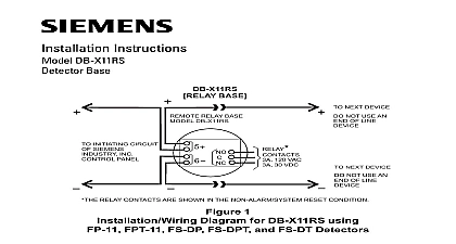
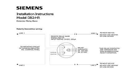
Installation Instructions DB HR Base RELAY BASE 1 1 NEXT DEVICE RELAY BASE DB HR NOT USE AN END LINE DEVICE INITIATING CIRCUIT SIEMENS INDUSTRY CONTROL PANEL 120 VAC 30 VDC RELAY CONTACTS ARE IN THE NON ALARM RESET CONDITION 2 NEXT DEVICE 2 NOT USE AN END LINE DEVICE 1 AND LINE 2 CAN BE EITHER LINE OF THE LOOP 1 Wiring Diagram Using HFP 11 Series and SFP 11 Series Detectors AND BASE PLACEMENT and base locations shall follow the drawings provided or approved Siemens Industry Inc or its authorized distributors This is extremely The detector placements shown on these drawings were chosen a careful evaluation of all facets of the protected area When drawings not available refer to Detector Placement section of detector Installation Instructions and to NFPA 72 National Fire Alarm Code and CAN ULC WIRING Model DB HR from Siemens Industry Inc is a polarity insensitive detector and works with HFP 11 HFPT 11 HFPO 11 SFP 11 SFPT 11 and SFPO detectors only Detectors should be interconnected as shown in Figure 1 wired to the DLC refer to DLC Installation Instructions P N 315 033090 FS refer to FS 250 Installation Operation and Maintenance Manual P N 315 or FDLC refer to FS 250C Installation Operation and Maintenance P N 315 049589C as applicable Line 1 and Line 2 can be either line of loop Note any limitations on the number of detectors and restrictions the use of remote devices permitted for each circuit SFPT 11 and SFPO 11 detectors are approved for use in Canada only Industry Inc Technologies Division Park NJ 315 033220 5 Building Technologies Ltd Safety Security Products Kenview Boulevard Ontario 5E4 Canada MOUNTING USING THE DB HR BASE detector is provided with a separate base which attaches to a standard 4 square or a 4 inch octagonal electrical box with the box size and depth by the NEC for the number and size of conductors used Wire size 14 AWG min 18 AWG to Figure 2 Route all wires outward from outlet box When the ALARM LED viewing is critical position the LED mark in the in the intended direction Route wires through the hole in the center of the base and mount base outlet box Make connections directly to the base terminals Refer to 1 and 2 for details After all bases are installed check wiring integrity To insure proper installation of the detector head into the base Route wires away from connector terminals Take up all slack in the outlet box Properly dress and position all wires flat against the base Check that screw terminals are tight LED WITH BASE O N O T P A I N T COVERS 2 the Base 315 033220 5