Siemens DB2-HR Detector Relay Base, Installation Instructions

File Preview
Click below to download for free
Click below to download for free
File Data
| Name | siemens-db2-hr-detector-relay-base-installation-instructions-5781643092.pdf |
|---|---|
| Type | |
| Size | 681.11 KB |
| Downloads |
Text Preview
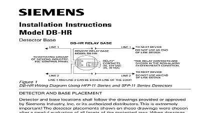
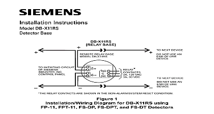
Installation Instructions DB2 HR Relay Base Insensitive wiring 1 RELAY BASE DB2 HR RATING 24VDC 200 A 1 NEXT DEVICE NOT USE AN END LINE DEVICE INITIATING CIRCUIT SIEMENS INDUSTRY CONTROL PANEL 120 VAC 30 VDC RELAY CONTACTS ARE SHOWN IN THE NON ALARM SYSTEM RESET CONDITION 2 1 2 X Wiring Isolator mode initiating circuit of compatible control unit BASE DB 11 DB 11E 8727C RL HC 2 NEXT DEVICE NOT USE AN END LINE DEVICE NEXT BASE NOT USE AN OF LINE DEVICE 120 VAC 30 VDC NOT USE AN OF LINE DEVICE NEXT BASE The relay contacts are shown after System reset which represents the non alarm condition Wires connected to TB3 TB4 must enter or exit electrical box on opposite side of wires connected TB1 if TB1 is used in an AC Power or Non Power Limited application 1 Wiring for Polarity Insensitive Detectors Inc Inc Inc Industry Inc Inc Infrastruct Infrastruct Infrastructureureureureure Infrastruct Infrastruct AND BASE PLACEMENT and base locations shall follow the drawings provided or approved by Industry Inc or its authorized distributors This is extremely important The placements shown on these drawings were chosen after a careful evalua of all facets of the protected area When drawings are not available refer to Placement section of detector Installation Wiring Instructions and to NFPA National Fire Alarm Code and CAN ULC S524 Model DB2 HR from Siemens Industry Inc is a polarity insensitive detector base is compatible with the detectors listed in Table 1 base should be interconnected as shown in Figure 1 and wired to the device loop of control panel Line 1 and Line 2 can be either line of the loop Note any limitations on the of detectors and restrictions on the use of remote devices permitted for each For maximum number of devices refer to the panel power calculations in the manual P N 315 033060 wire size AWG minimum AWG maximum larger than 14 AWG can damage the connector Industry Inc Infrastructure LIMITED WIRING compliance with NEC Article 760 all power limited fire protective signaling conductors must separated a minimum of 1 4 inch from all of the following items located within an outlet box light 1 or non power limited fire protective signaling conductors meet the above the requirements the following guidelines must be observed when this relay base module BARRIER Module Barrier must be used when the DB2 HR relay contacts are connected to non power lines Break apart the barrier to the correct size and shape shown in Figure 2 for the 4 inch box Install the barrier diagonally into the back box to create two separate compartments the backbox to separate the wires as shown in Figure 2 SQUARE BOX 1 8 INCHES DEEP 6 OFF THIS WHEN A 4 INCH BOX 2 the Control Module Barrier ENTERING OUTLET BOX Limited Wiring power limited wiring must enter the outlet box separately from the electric light power Class or non powered limited fire protection signaling conductors For the DB2 HR wiring to terminal TB3 and TB4 must enter the outlet box separately from wiring to terminal block TB1 IMPORTTTTTANANANANANTTTTT Minimize the length of wire entering the outlet box IMPOR IMPOR IMPOR IMPOR Industry Inc Infrastructure MOUNTING USING THE DB2 HR BASE detector is mounted on the DB2 HR base which attaches to a standard 4 inch square box with the box size and depth required by the NEC for the number and size of used Wire to the terminal blocks as shown in Figure 1 Wire size max 14 AWG 18 AWG After all bases are installed check wiring integrity To insure proper installation of the detector head into the base sure that existing wires are away from connector terminals that screw terminals are tight LED WITH BASE FOR O N O T P A I N T COVERS 3 the Detector into the DB2 HR Base Industry Inc Infrastructure SECURITY DISCLAIMER provides a portfolio of products solutions systems and that includes security functions that support the secure of plants systems machines and networks In the field of Technologies this includes building automation and control safety security management as well as physical security order to protect plants systems machines and networks against threats it is necessary to implement and continuously a holistic state of the art security concept Siemens only forms one element of such a concept are responsible for preventing unauthorized access to your systems machines and networks which should only be to an enterprise network or the internet if and to the such a connection is necessary and only when appropriate measures e g firewalls and or network segmentation are place Additionally Siemens guidance on appropriate security should be taken into account For additional information contact your Siemens sales representative or visit https portfolio undergoes continuous development to make it secure Siemens strongly recommends that updates are as soon as they are available and that the latest versions are Use of versions that are no longer supported and failure to the latest updates may increase your exposure to cyber Siemens strongly recommends to comply with security on the latest security threats patches and other related published among others under Industry Inc Infrastructure PAGE HAS BEEN LEFT INTENTIONALLY BLANK Industry Inc Infrastructure PAGE HAS BEEN LEFT INTENTIONALLY BLANK Industry Inc Infrastructure Industry Inc Infrastructure Park NJ Canada Ltd North Service Road East Ontario 0H6 Canada Document ID A6V10327325 en b