Siemens Desigo Fire Safety Fire terminal and equipment, data sheet

File Preview
Click below to download for free
Click below to download for free
File Data
| Name | siemens-desigo-fire-safety-fire-terminal-and-equipment-data-sheet-9867431502.pdf |
|---|---|
| Type | |
| Size | 870.40 KB |
| Downloads |
Text Preview
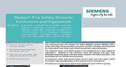
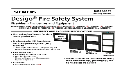
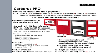
Data Sheet Safety Security Products Fire Safety System Terminal and Equipment FTI2001 U1 FCM2018 U2 FCM2019 U2 FHB2001 U1 R1 FHB2002 U1 R1 R2 FHD2002 U2 R2 FN2001 U1 and FHD2005 U1 AND ENGINEER SPECIFICATIONS Contains the following system components Operating unit Model FCM2018 U2 or Model FCM2019 U2 Fire Terminal Module Model FTI20001 U1 SafeDLINK Module Model FN2001 U1 One height unit back box Models FHB2001 U1 R1 One height unit outer door FHD2001 U2 R2 Inner door Model FHD2005 U1 Multi use main system interface modules Power Alarm Supervisory Silenced Ground Fault Audibles On Trouble system status LEDs with Alarm as having a distinctive LED Partial system disable LED Audible Status LEDs and 10 configurable LEDs Model FCM2019 U2 contains one 1 set of 48 light emitting diodes LEDs System control menus Context sensitive menu Four way navigation buttons and extended views capability User prompted large softkey buttons for multi programming options and system control operating sequence Seven 7 spare user programmable buttons Slide in labels appear adjacent to system operation buttons FTI 2001 connects to 24VDC power source via screw terminal Ribbon cables connect to the operating unit Display shows eight 8 lines 40 characters per row Plain text display with two 2 lines of information per Alarm event Context sensitive soft keys Additional display of location specific reaction texts can be stored Several events are displayed simultaneously Operating access for full system operation via password Several operator terminals are possible for each fire detection system to 16 nodes max Optional accessories available Digital Alarm Communication Transmitter DACT RS module Model FCA2016 U1 Remote terminal display Model FT2014 U2 R2 Remote terminal display with control Model FT2015 U2 R2 Remote peripheral module Model FCA2018 U1 Overview Fire Terminal and equipment connects to a network that can be configured for system view or specific panel local view This allows the operator for system control events control system notification circuits NACs and reset the system Industry Inc Technologies Division 2 4 3 4 back lit LCD Style 4 and Style 7 wiring configuration Requires the SafeDLINK module Model to connect to FDnet Ethernet port connectivity for system and Firmware software Compatible with built in EEPROM system firmware Can be configured for system global view control Global annunciation and control capability System operation and indication Convenient context and status sensitive via soft keys Alphanumeric pad UL 864 9th Edition Listed ULC Listed FM CSFM and NYC Fire Dept Approved Fire Terminal and equipment allows for to the Remote Peripheral Module Model and or the Remote Terminal Displays FT2014 U2 R2 FT2015 U2 R2 Fire Terminal contains the site specific program which is created in the custom programming tool Fire Terminal and Equipment 6803 Fire Terminal Model FT2050 consists of the Fire Board Model FTI2001 U1 the Operating Model FCM2018 U2 or Model FCM2019 U2 and one height unit enclosure Fire Terminal contains one 1 2 4 3 4 Video Array VGA monochrome LCD screen and diodes LEDs for displaying system An audible will sound when there are events on the system display is surrounded by keys that are used to the displayed information and to navigate these screens Keys are also provided to obtain and to enter into the menu features of each unit display of each operating unit categorizes events by providing a separate event tab for Alarm Gas Alarm and Trouble events The quantity of active of each type is listed in each event tab The display two 2 full lines of text message for each event event can have a 40 character custom message the location for a given event In addition to the message the system displays the category of the active e g Automatic Alarm Water Flow Manual etc category means more to responding officials than model to two 2 events can be displayed at a time When more two 2 events are present the up and down arrow allow the end user to scroll up and down the list of A progress meter on the side of the list indicates the of the list of events and the location in the list New events are indicated by a flashing point interface also provides a completed menu for system status reports with a Preview directly on the screen before sending the report the printer Maintenance menu is accessed by password When end user enters this mode the LCD will be enabled the user to enter a password System control the maintenance menu uses easy to read touch Fire Terminal and equipment are FM 3010 CSFM and FDNY 6104 Approved and Humidity Range are UL 864 9th Edition Listed for operation the temperature range of 32 to 120 0 to and a relative humidity of 93 2 at a of 90 3 32 2 Documentation Sheet Number for Ordering S54400 A58 A1 Fire Terminal S54400 C40 A1 Operating Unit S54400 C41 A1 Operating Unit with LED S54400 B47 A1 One Height Unit Back Box black S54400 B47 A2 One Height Unit Back Box red S54400 B48 A1 Two Height Unit Back Box black S54400 B48 A2 Two Height Unit Back Box red S54400 B49 A1 One Height Unit Outer Door black S54400 B49 A2 One Height Unit Outer Door red S54400 B50 A1 Two Height Unit Outer Door black S54400 B50 A2 Two Height Unit Outer Door red This marketing data sheet is not intended to be used for system design or installation purposes the most up to date information refer to each product installation instructions Industry Inc Technologies Division Safety Fernwood Road Park NJ 07932 973 593 2600 908 547 6877 www USA Siemens com Desigo Fire Safety in U S A Safety Kenview Boulevard Ontario 5E4 Canada 905 799 9937 905 799 9858 2013 sheet dated 2 13 3