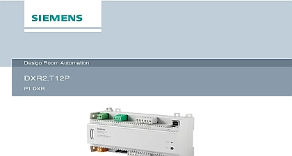
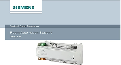
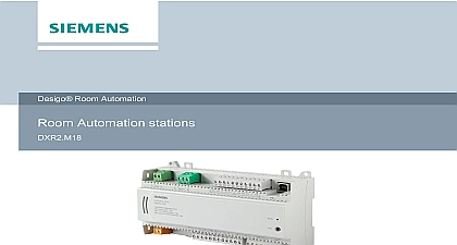
Siemens Desigo Room Automation Station P1 DXR DXR2 T18P Submittal Sheet

File Preview
Click below to download for free
Click below to download for free
File Data
| Name | siemens-desigo-room-automation-station-p1-dxr-dxr2-t18p-submittal-sheet-4960137852.pdf |
|---|---|
| Type | |
| Size | 813.39 KB |
| Downloads |
Text Preview
Room Automation DXR Automation station which migrates P1 TEC controller technology to the latest DXR2 platform Using existing P1 network wiring and panels the firmware generates P1 TEC points for the configured template KNX PL Link bus to connect sensors actuators and operator units P1 Protocol Communication USB interface Operating voltage AC 24V Technologies Proven pre loaded applications Operational modes Comfort Standby Economy Protection and so on Applications Coil Unit FCU FAN COIL 2 Pipe CW HW and HW Valves FAN COIL 4 Pipe CW and HW Valves FAN COIL staged Cooling and staged Heating FAN COIL with CW and staged Electric Heat FAN COIL VENT with CW HW and Outside Air Damper OAD control FAN COIL VENT with CW ELEC and OAD control FAN COIL UNIT VENT with DX HW and OAD control FAN COIL UNIT VENT with DX ELEC and OAD control Pump HP Variable Speed Two Stage Elec Heat and One Stage Elec Rad with OAD HP Variable Speed Water Source HW Heat and Modulating Elec Rad with OAD HP Single Stage One Stage Elec Heat and HW Rad with OAD HP Multi Stage Two Stage Elec Heat and HW Rad with OAD HP Multi Stage Hot Gas Reheat One Stage Elec Heat and HW Rad with OAD HP Multi Stage Ground Source Hot Gas Reheat One Stage Elec Heat and HW Rad with Chilled Beam cooling only cooling and heating 4 pipe or cooling heating 2 pipe Radiator Baseboard hot water steam or electric stages Demand Control Ventilation with separate flow setpoints for each operational mode Chilled beams and Radiator control Single multiple or variable speed terminal fan control Optional terminal DX chilled water hot water or chilled heated valve 2 pipe or 4 pipe Configurable operating modes heating cooling warm up cool down flush purge and so Applications Application Options selected application and its parameters as well as input and output configuration determine room automation station s functionality RS 485 P1 Protocol USB connection for service and commissioning application and firmware download The following functions are available with the KNX PL Link bus Communication with room operator units sensors actuators Plug and play connection of Siemens field devices with KNX PL Link Technologies DXR2 T18 Summary Number DXR2 T18 Room DI 4 UI Station DO Triacs 4 AO 0 to V Number OHM Resistor Kit Documentation and mounting DXR Room Automation Station Installation datasheet and commissioning Migration 24 V IP 24 V MS TP VAV Start up Procedures FPB Start up Procedures FCU Start up Procedures Balancing Procedure DXR TEC Variable Air Volume and Powered Box Migration PDF DXR TEC Variable Air Volume and Powered Box Migration HTML Help DXR TEC Fan Coil Unit Guide PDF DXR TEC Fan Coil Unit Guide HTML Help DXR TEC Heat Pump Guide PDF DXR TEC Heat Pump Guide HTML Help ID Unit Datasheet sensors and room operator units for PL Link KNX S mode and KNX LTE Mode Data Data in 180 mm x 4.11 in 104.5 mm x 2.34 in 59.5 mm 3 lb 1.35 kg Supply voltage 2 Power Source 24V 15 20 Hz A 96 VA maximum Technologies DXR2 T18 Power VA for Transformer Design Model Load Load Load all Outputs Output A Each 24V 24V Load Load Allowed PL Link 50 mA 24V 2.4 Devices x 6 48 for the Triac outputs must be reduced if the max load of 18 VA is required for AC 24 V supply on the DXR2 x18 calculate the total VA add the Base Load number of Triacs field supplies KNX PL Link cannot exceed the maximum power consumption See Wiring Guidelines for Field Panels Equipment Controllers 125 3002 for more information Sensor Measurement Measurement PT1K 375 PT1K 385 Ni1000 1 Ni1000 DIN NTC3K NTC10K 1 NTC100K 1 0 to 10V 0 to 10V 0 to 100 resistance for closed contacts resistance for open contacts than 100 than 50 k 17 V typical mA typical 7 mA initial current Inputs 1000 2500 10 K 100 K default Inputs query voltage query current Outputs to 10V Outputs Switching outputs triacs voltage load mA maximum side Triac closes the contact to AC 24V 24V mA 6VA per output proof Technologies DXR2 T18 24V output for field devices 1 V voltage load against overload 24V mA 2.4 W proof Network 2.0 PL Link Connections screw terminals type RS485 isolation Yes rates 4800 P1 Protocol Type B isolation No use isolator for connection to grounded USB host see 3 rate 12 Mbps Full Speed USB 1.1 and USB 2.0 compatible KNX TP1 PL Link galvanic isolation rate 9600 bps power 50 mA against faulty wiring at maximum AC 24V wire or copper strands with ferrules x 0.6 mm diameter to 2.5 mm2 22 to 14 AWG or x 0.5 mm diameter to 1 mm2 24 to 18 AWG strands without ferrules x 0.6 mm diameter to 2.5 mm2 22 to 14 AWG or x 0.5 mm diameter to 1.5 mm2 24 to 16 AWG screws 1 8 inch blade tightening torque 0.6 Nm 0.44 lb ft lengths for signals PL Link 80 m 263 ft with internal bus power 3,280 ft 1,000 m lines 263 ft 80 m Network and Power Wiring 1 configuration per foot type type or 2 twisted pair Pair 1 red black Pair 2 yellow white AWG solid bare copper Minimum pF foot or less foil with drain wire Vrms CMP 75 C or higher Vrms FT6 75 C or higher 18 AWG STP CMP Belden 6320FE 8771000 Technologies DXR2 T18 CAUTION safety regulations to comply with national safety regulations may result in personal injury and property Observe national provisions and comply with the appropriate safety regulations Conditions and Protection Classification ambient conditions and storage Operation 25 13 158 humidity 5 rh 95 rh 5


