Siemens DSC Dual Sync Control Unit, Installation Instructions and Wiring

File Preview
Click below to download for free
Click below to download for free
File Data
| Name | siemens-dsc-dual-sync-control-unit-installation-instructions-and-wiring-1452063879.pdf |
|---|---|
| Type | |
| Size | 683.25 KB |
| Downloads |
Text Preview
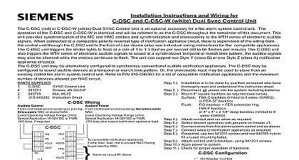
Installation Instructions and Wiring for Dual Sync Control Unit DSC Dual SYNC Control Unit is an optional accessory for a fire alarm system control unit This unit provides synchro of the MC and HMC strobes and synchronization and silenceability to the MTH series of electronic audible When connected to a compatible polarity reversal type of notification appliance circuit there is supervision of the from the control unit through the DSC unit to the End of Line device also see individual wiring instructions for the appliances The DSC unit triggers the strobe lights to flash at a rate of 1 to 1.1 flashes per second 60 to 66 per minute The DSC unit also triggers the MTH series of electronic audible signals to sound in a synchronized or march time pattern the audible signals may also be silenced while the strobes continues to flash The unit support two Style Y class B or one Style Z class A notification appliance circuit s DSC unit may be alternatively configured to synchronize conventional audible notification appliances The DSC may configured to sound audible devices at a temporal or march time pattern Or the silenceable input may be used to from an existing coded fire alarm system control unit Refer to P N 315 096363 for a list of compatible notification and the maximum number of devices allowed per NAC circuit SUPPLIED Instruction Sheet Control Unit 8 32x3 8 8 32 Wiring Control control panel non pulsing or pulsing NAC or slaved NAC Operating Voltage Range Limits Application 16 32V DC or FWR Amp If required Power control panel non pulsing Nonsilenceable Operating Voltage Range Limits Application 16 32V DC or FWR Amp plus output notification appliance load compatible notification appliances Amp max load not to exceed NAC Rating by NAC as circuit 1 above to be installed in accordance with all local electrical codes block will accept a maximum of 12 AWG wiring Installation Instructions for proper strobe installation Installation Instructions for proper signal installation the silenceable NAC input is not used or when separate horn and operation is not required cut wire jumper W2 on circuit board on firmware version 1.1 or later maximum line impedance per circuit is 30 ohms DSC Control Units were only tested to the operating voltage limits of and 32V Do Not apply 80 and 110 of these values for system 1 is to be done by qualified personnel who have read and understood this instruction sheet 2 Disconnect all power into the system including batteries 3 Mount 4 square backbox as required see below SHBB R surface box SBB R surface box backbox FER extension ring 4 Attach conduit and run wires as required 5 Select desired operation with jumpers on header J1 6 Connect wires from fire alarm system control unit as shown 7 Connect wires to notification appliances as required 8 required use two 941201 screws and two 940705 nuts to unused mounting holes 9 Attach control unit to backbox using 941201 screws 10 Apply power to system 11 Check for proper operation of functions Configuration Control Control Input Response Input Response Strobe SYNC Audible Devices Audible Devices Audible Pattern Time Audible Pattern three pulse temporal is to be used for use only Mounting Dimensions Industry Inc Technologies Division Park NJ 315 545222 12 PAGE 1 OF 4 Style Y Class B Diagram for SYNC Appliances Style Z Class A Diagram for SYNC Appliances The Silenceable N A C controls the silencing of the audible Sync appliances The Silenceable N A C is required only if audible SYNC appliances are used The Non Silenceable N A C supervises and powers the associated Output circuit and appliances The delayed Sil Input allows the Sil Input to be connected to a pulsed N A C with an off time up to 4 seconds When silenceable NAC is not used see note 5 on page 1 Style Y Class B Diagram for SYNC Appliances Style Z Class A Diagram for SYNC Appliances The Silenceable N A C controls the silencing of the audible Sync appliances The Silenceable N A C is required only if audible SYNC appliances are used the silenceable NAC input is not used or when separate horn and strobe operation is not required wire jumper W2 on circuit board only on firmware version 1.1 or later The Non Silenceable N A C supervises and powers the associated Output circuit and appliances The delayed Sil Input allows the Sil Input to be connected to a pulsed N A C with an off time up to 4 seconds Up to 600 DSC control units may be slaved from the master DSC control unit number is determined by the master Non Silenceable N A C current divided by the slave input current ie 3A 005A 600 Cascading of the output of a slave to the input of another slave is not recommended 315 545222 12 PAGE 2 OF 4 Style Y Class B Style Z Class A Diagram for Conventional Appliances Diagram for Conventional Appliances The above configuration will allow conversion of a steady N A C to temporal or march time The second steady N A C is optional in the Style Y diagram The Non Silenceable N A C supervises and powers the associated Output circuit and appliances For Compatible notification appliances see the installation instructions for the Steady N A C The Sil Input is not used Additional DSC units may be slaved as shown below two Style Y Steady N A C s are used both must be from the same control unit signal expansion control unit Expansion Style Y Class B Diagram for Conventional Appliances Expansion Style Z Class A Diagram for Conventional Appliances The above configuration will allow conversion of a steady N A C to coded following the existing Coded N A C The second steady N A C is optional in the Style Y diagram The Steady N A C supervises and powers the associated Output circuit and appliances For Compatible notification Appliances see the installation instructions for the Steady N A C Up to 600 DSC control units may be slaved from the Coded N A C two Style Y Steady N A C s are used both must be from the same control unit signal expansion unit number is determined by the Coded N A C current divided by the slave input current ie 3A 005A 600 315 545222 12 PAGE 3 OF 4 page has been left intentionally blank 315 545222 12 PAGE 4 OF 4 ID A6V10239292