Siemens FC2005 FC901 Installation Instruction

File Preview
Click below to download for free
Click below to download for free
File Data
| Name | siemens-fc2005-fc901-installation-instruction-3914768250.pdf |
|---|---|
| Type | |
| Size | 2.31 MB |
| Downloads |
Text Preview
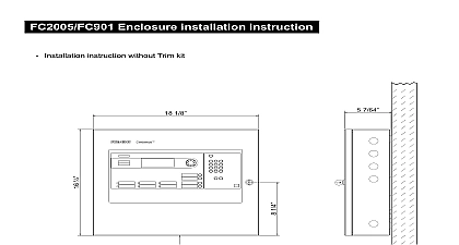
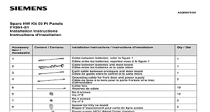
FC2005 FC901 installation instruction diagram clearance declaration Technologies Safety Security Products installation instruction and separate parts instruction between batteries refer to figure 1 between batteries and main board refer to figure 1 figure 2 between City tie board and main board refer to figure 2 cable between enclosure and main board refer to figure 1 and 2 cable for front door and power supply to figure 1 bracket left refer to figure 1 bracket right refer to figure 1 ties screws refer to figure 1 screws refer to figure 2 for City tie board refer to figure 2 supply MOV Metal Oxide Varistor refer to figure 2 cell refer to figure 1 supply refer to power supply installation instruction sheet with power supply door hinge axis lock pin refer to Detail A door hinge axis refer to Detail A for NAC refer to Detail C Item 3,6,7,11 S1and S2 are not delivered with the FC901 and FC2005 And should be ordered separately notes Mount the batteries with battery brackets Mount the power supply MOV then mount the power supply to the enclosure Mount the City tie module onto the main board according to the Figure 2 City tie module is optional Connect the cables to the corresponding position marked on the drawing The power supply input cable and output cable are not included in the FC901 and FC2005 package Tie the cables to the enclosure with cable tie refer to the Figure 1 Cable tie features Mount the Main board assembly onto the Enclosure according to Figure 3 Mount the Lock pin to the Front door axis Both are included in the Enclosure package Technologies Safety Security Products ID A5Q00039713A 1 12 installation instruction installation instruction Power supply and City tie PCB assembly installation instruction attention to the battery polarity at 2.1 and 2.2 A and 5.1 1 tie feature supply output 1 Installation instruction Front view with front door open A Front door hinge and lock pin installation instruction B tie supply DC input 2 Installation instruction Main board assembly back view Technologies Safety Security Products ID A5Q00039713A 2 12 installation instruction installation instruction tie cable Main board and EOL installation instruction left to right 1 to 4 Output 2 to 3.2 Output 1 to 3.3 B City tie cabling C 3 Main board assembly installation instruction N C NAC EOL installation instruction Technologies Safety Security Products ID A5Q00039713A 3 12 installation instruction installation instruction supply MOV Metal Oxide Varistor Installation instruction 1 Bend the MOV connector pin to the picture for an example 2 Fix or weld the MOV onto the power input the picture as reference 3 Fix the AC input cable and screws on connector Take the picture as reference Technologies Safety Security Products ID A5Q00039713A 4 12 installation instruction installation instruction instruction without Trim kit 1 8 7 64 Control Unit at convenient height access to display controls Technologies Safety Security Products ID A5Q00039713A 5 12 installation instruction installation instruction instruction with Trim kit 1 4 1 4 MAX Control Unit at convenient height access to display controls Technologies Safety Security Products ID A5Q00039713A 6 12 installation instruction SYSTEM CONNECTION DIAGRAM SYSTEM GENERAL SPECIFICATION temperature 32 120 0 49 humidity Up to 93 90 32 be installed in a indoor dry protected environment only Power Supply 120VAC 60 Hz or 220 VAC 50 Hz 2.0A Max 26VDC 6.5A Max current 6.5A 2 hours Max and Regulated Power Supply lead acid battery set charged voltage 27.8 VDC low battery disconnect voltage 19.2 charge current 0.45A capacity 12AH to 18AH Addressable Device Circuits VDC Max er limited current 0.07A RMS w ire loop resistance 50 o Style 4 Class B or one Style 6 Class A circuit 50 addressable devices Tie Circuits Input 26 VDC 18 28 VDC for battery Max 0.4A Tie Output 1 output voltage 19 28VDC open circuit condition current 1mA trip current 400mA coil plus w ire resistance 22.5 line Output 1 output voltage 19 28VDC open circuit condition output voltage 0V output voltage 19 28 VDC open circuit condition w ire resistance 2 5K short circuit current 25mA line Output 2 output voltage 19 28VDC open circuit condition output voltage 19 28 VDC open circuit condition w ire resistance 2 5K short circuit current 25mA Circuits er limited for short or open circuit conditions to FCC part 68 RJ31X connection Digital Alarm Communication Receiver DACR list compatibility list module ell To reduce the risk of fire use only No 26 AWG larger telecommunication line cord Power Outputs Non resettable power output er limited status 0.75A stand by 0.05A 19 to 28VDC 0.1 VAC Application Resettable power output er limited status 0.75A stand by 0.05A 19 to 28VDC 0.1 VAC Application Relays er limited programmable relay non programmable relays Trouble Supervisory Alarm rating 2A 30VDC maximum C contact Appliance Circuits er limited Draw 2.5A 2.0A 1.5A 1.0A 0.5A voltage 16 to 32VDC ripple 0.1VAC for special application only o Style Y Class B or one Style Z Class A Max Current 2.5A Line Resistance Technologies Safety Security Products ID A5Q00039713A 7 12 installation instruction SYSTEM CONNECTION DIAGRAM SYSTEM CONNECTION DIAGRAM All the wiring must be in according with local codes and National Electric Code Technologies Safety Security Prod