Siemens FCA2018-U1 Remote Peripheral Module, Installation Instructions

File Preview
Click below to download for free
Click below to download for free
File Data
| Name | siemens-fca2018-u1-remote-peripheral-module-installation-instructions-1458372609.pdf |
|---|---|
| Type | |
| Size | 674.75 KB |
| Downloads |
Text Preview
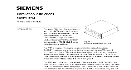
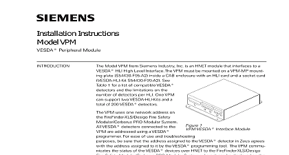
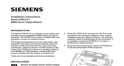
Installation Instructions FCA2018 U1 Peripheral Module Model FCA2018 U1 from Siemens Inc is an Universal Fire module that interfaces to a parallel printer It must be where access to the FS20 UFP network and 24VDC power output are available 1 Remote Peripheral Module FCA2018 U1 is required whenever a printer is needed It translates UFP messages into a standard Centronics printer interface When used conjunction with the PAL 1 it provides a supervised logging printer meeting the of NFPA 72 Proprietary or UL 1076 Security systems For NFPA 72 Auxiliary or Remote Station applications any UL EDP listed Centronics parallel may be used See notes 2 3 and 4 on Figure 3 of the PAL 1 includes paper out paper jam printer off line power off and printer disconnected be connected to the UFP Style 4 or Style 6 diagnostic LEDs to indicate failure of the UFP or the CPU It also a power on indicator a reset switch in the event that the FCA2018 U1 requires a reset be mounted on any smooth surface within 6 feet of the PAL 1 features are as follows Industry Industry Industry Inc Inc Inc Industry Inc Industry Inc TTTTTececececechnologies Di Di Di Division Di a system event occurs the Operating Unit sends a print message to the via UFP The FCA2018 U1 is responsible for printing the message The contains a buffer to ensure that events that occur at a rate faster than the can print them are not lost and Indicators FCA2018 U1 continu monitors the to the PAL 1 for any errors would inhibit printing errors that are are communi to the Operating via UFP for annuncia Restoration to the condition is also and communi to the Operating Print messages that at the FCA2018 U1 a printer fault are in the buffer UFP side panel of the contains one switch three LEDs termination switch and UFP address switch as in Figure 2 reset switch is located the top of the panel the reset switch the FCA2018 operation FAIL FAIL GND INPUT 3 1 2 2 2 SIDE SIDE 2 Side Panel Detail FAIL FAIL ON When illuminated indi that power for the FCA2018 U1 is to the module OFF When illuminated indi that the module microprocessor failed OFF When illuminated indi that the UFP communication with FCA2018 U1 has terminated three position switch located directly beneath the LEDs on the UFP side of the is used to set the UFP network address of the FCA2018 U1 Industry Inc Technologies Division connecting either the printer power or the UFP the network address must be for the FCA2018 U1 using the three position switch Refer to Figure 2 for the of the switch The address for the FCA2018 U1 must be the same as the selected for it in the FS20 Configuration Tool To increment each digit of the press the button above the desired digit to decrement each digit press button below the desired digit The range of allowable addresses is from 001 8 leading zeros must be used the FCA2018 U1 is located at the end of the UFP network Style 4 only the termi switch must be set to ON Otherwise it must be set to OFF 3 The FCA2018 U1 Terminal Block Covers terminal block covers are provided with the FCA2018 U1 Each comes as two parts a lower bracket which has a inch conduit opening and a cover the lower bracket to each end of the FCA2018 U1 using four of the 10 nuts in the FCA2018 U1 hardware kit Reserve the covers and the remaining until the FCA2018 U1 is mounted and wired the FCA2018 U1 to either the wall or desk where the PAL 1 is located Use four mounting holes in the lower bracket or EDP LISTED PRINTER VAC Hz SUPPLIED WITH FCA2018 U1 LIMITED The maximum distance from the FCA2018 U1 to the PAL 1 is 6 feet The two modules must be in the same room For NFPA 72 Local Auxiliary and Remote Station configurations connect the output of the FCA2018 U1 to any EDP listed printer The printer must support the EPSON FX command set For NFPA 72 Proprietary of UL 1076 configurations use printer SIEMENS Model PAL 1 a UL listed for fire Centronics parallel printer The printer is supervised for AC loss off line paper out paper jam and connection to the FCA2018 U1 After loading the paper in the PAL 1 printer turn off the power and follow the steps below While pressing the LOAD PARK button turn on the power to the PAL 1 printer Keep pressing the LOAD PARK button for 5 seconds Release the LOAD PARK button The current setting will print When printing is completed the ON LINE indicator will be lit If the ON LINE indicator is not lit press the ON LINE button 4 The Printer To The FCA2018 U1 Industry Inc Technologies Division all system power before installation first battery then AC To power up the AC first then the battery PAL 1 is connected to the FCA2018 U1 with a standard PC printer cable This is supplied with the FCA2018 U1 Connect the PAL 1 to the FCA2018 U1 using cable The two ends of the cable are different ensuring proper connection See 4 FCA2018 U1 requires 24VDC to operate This power is available on the Aux Terminal X1001 on the FS20 Periboard See Figure 5 for wiring details 18 AWG min 12 AWG max Power limited to NFPA72 NEC 760 No end of line device 50 max total wire Refer to FS20 Product Data P N A6V10315015 ground fault detection 5 Power To The FCA2018 U1 LIMITED FC360 X1 N FC360 X1 P GROUND INPUT FCA2018 U1 can be connected to the UFP Style 6 or Style 4 Refer to the FS20 for the proper Style If the FCA2018 U1 is connected at the end care be taken to properly terminate the UFP See Figure 6 for the wiring instructions the FCA2018 U1 is connected as Style 6 and Figure 7 when the FCA2018 U1 is as Style 4 LIMITED Module NOT USE NOT USE UFP BLOCK UFP BLOCK MODULE MODULE 18 AWG min 12 AWG max 2000 ft max between RS485 and FCA2018 U1 Use twisted pair or shielded pair Terminate shield at one end Power limited to NFPA72 NEC 760 Reference RS485 Module Instructions ID A6V10334252 6 Style 6 Wiring Configuration Industry Inc Technologies Division LIMITED NEXT UFP Module NOT USE UFP BLOCK No end of line resistor Termination set to except on the is at the end of network where the is set to ON 18 AWG min 12 AWG max 2000 ft max between RS485 and FCA2018 U1 Use twisted pair or shielded pair Terminate shield at one end Power limited to NFPA72 NEC 760 Reference RS485 Module Instructions ID A6V10334252 7 Style 4 Wiring Configuration PAL 1 requires a standby power source in the event of the loss of primary input power mains Refer to Figure 8 for the connection of a UPS to meet this requirement All wires 14 AWG min insulation Wiring to the printer must 14 AWG min 600V in conduit