Siemens FCM-6 LCM-8 SCM-8 Control Module LED Control Module Switch Control Module, Installation Instructions

File Preview
Click below to download for free
Click below to download for free
File Data
| Name | siemens-fcm-6-lcm-8-scm-8-control-module-led-control-module-switch-control-module-installation-instructions-9645072831.pdf |
|---|---|
| Type | |
| Size | 785.25 KB |
| Downloads |
Text Preview
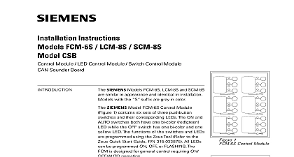
Installation Instructions FCM 6 LCM 8 SCM 8 CSB Module LED Control Module Switch Control Module Sounder Board 1 Control Module 2 LED Control Models FCM 6 LCM 8 and SCM 8 from Industry Inc are similar in appearance and in installation FCM 6 Control Module Figure 1 contains six of three pushbutton switches and their corre LEDs The ON and AUTO switches both one bi color red green LED while the OFF has one bi color and one yellow LED The of the switches and LEDs are pro using the Zeus Tool Refer to the Zeus Start Guide P N 315 033875 All LEDs can be ON OFF or FLASHING The FCM is for general control requiring ON OFF AUTO LCM 8 LED Control Module Figure 2 eight pairs of LEDs Each pair contains one red green and one yellow LED The func of the LEDs are programmed using the Zeus Refer to the Zeus Quick Start Guide P N 315 All LEDs can be programmed ON OFF or These LEDs are used for fire system annunciation SCM 8 Switch Control Module Figure 3 eight switches and eight pairs of LEDs pair contains one bi color red green and one LED The functions of the switches and LEDs programmed using the Zeus Tool Refer to the Quick Start Guide P N 315 033875 All LEDs be programmed ON OFF or FLASHING The is used for manual control of the fire system 3 Switch Control Inc Inc Inc Industry Inc Inc TTTTTececececechnologies Di Di Di Division Di 315 033040 5 Model CSB CAN Sounder Board from Siemens Inc P N 500 033130 is an optional module can be ordered separately It contains a sounder that can be used with the SCM 8 or FCM 6 to audible feedback to indicate that a switch closed and communication was successful The CSB no programming 4 Sounder Board modules mount on an ID MP mounting plate which is then mounted on the inner of a CAB enclosure or the outer door of a REMBOX enclosure The mounting plate hold either 4 SCMs LCMs or 2 FCMs or 1 FCM and 2 SCMs LCMs Controls and Indicators The FCM contains six sets of three pushbutton switches and their corresponding Pressing any of the six ON OFF or AUTO switches generates a unique CAN on the bus to the NIC that indicates which switch was pressed A CAN from the NIC to the FCM produces a preprogrammed output to the LED ON FLASHING or OFF An open collector is provided for to the CAN Sounder Board CSB a separate audio module The CSB an audible feedback to indicate that the switch closed properly and that between the FCM and NIC was successful Controls and Indicators The LCM contains eight pairs of LEDs A CAN message from the NIC to the LCM a preprogrammed output to any of the corresponding LEDs ON FLASH or OFF Controls and Indicators The SCM contains eight switches and eight pairs of LEDs Each switch is associated a pair of LEDs Pressing of any of the eight switches generates a unique CAN on the bus to the NIC that indicates which switch was pressed A CAN from the NIC to the SCM produces a preprogrammed output to the LED ON FLASHING or OFF An open collector is provided for to the CAN Sounder Board CSB a separate audio module The CSB an audible feedback to indicate that the switch closed properly and that between the SCM and NIC was successful Controls and Indicators The CSB contains a sounder buzzer that sounds when any switch on an FCM or is pressed Only one CSB is required for audible feedback more can be con to increase the volume if needed the board address for each FCM LCM SCM using both of the ten position rotary located on the back of the board See Figure 5 Each of these addresses be a sub address of the NIC and must be the same as the addresses assigned the Zeus Programming Tool The CSB does not require address setting setting the address label each switch or LED When viewed from the front of the FCM LCM SCM the labels are on the left and the control switches and are on the right to the Zeus configuration for the address of each module and its functions the label strip from its slot and type or print a brief function for each switch completing the label strip insert in back into its slot See Figure 6 Industry Inc Technologies Division 315 0033040 5 8 8 SWITCHES 5 LCM 8 SCM 8 Address Switches And Cable 6 A Label Into The Back Of The FCM 6 LCM 8 and SCM 8 to Figure 7 mounting bracket Model ID MP so the words UP are at the top each FCM LCM SCM in the desired on the mounting bracket aligning two studs in the smaller holes on the Secure with a 10 32 nut on each stud all of the positions on the mounting plate not filled with FCM LCM SCM modules a Control Module Blank Plate BCM in of those positions by aligning the two in the smaller holes on the bracket securing with a 10 32 nut on each stud the filled mounting bracket over the studs on the back of the inner door so the modules face through the opening secure with a 10 32 nut on each stud steps 1 through 4 until all FCM modules are installed 7 FCM 6 LCM 8 Modules a blank plate Model ID SP in unused spaces on door secure with 10 32 nuts Refer to Models CAB2 BD RD CAB3 BD RD Installation Instructions P N 315 033008 for more Industry Inc Technologies Division 315 033040 5 Sounder Board to Figure 8 CSB is normally positioned at the last FCM LCM or SCM If desired multiple can be installed The CSB mounts on the stud of the FCM LCM SCM module it connects to the position of the CSB on the ID MP Mounting Plate This is at the last FCM LCM or SCM module necessary remove 10 32 nut from stud of FCM LCM SCM where CSB is be mounted mounting hole on the CSB over stud with 10 32 nut supplied with FCM LCM SCM 1 1 1 1 1 1 8 The CSB to Figure 9 all system power before installation first battery then AC To power up the AC first then the battery FCM LCM SCM module is a node in the CAN bus FCM LCM SCM connects through the CC 5 CC 2 CAN bus via a plug cable to the NIC or to another FCM LCM SCM module to 99 FCM LCM SCM modules in any combination can be connected the CAN bus of each NIC FCM LCM SCM CSB module is shipped with one CCS cable Industry Inc Technologies Division 315 0033040 5 TERMINATOR 110 134215 WITH NIC C 0 0 0 0 0 0 0 0 CC 5 CC 2 P3 CCL 0 0 0 0 0 0 0 0 0 0 0 0 0 0